


Installation __________________________________________________________________________
RF-MCGARDPRO
Hubbell Power Systems, Inc.
–
RFL™
Products
July 1, 2022
©2022 Hubbell Incorporated
3-23
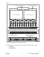
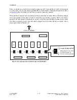
Form A outputs are selected by moving the jumper pair UP (towards the A) and Form B outputs
are selected by moving the jumper pair DOWN (towards the B). The Relay Output Unit shown
in
has all jumpers in the Form A position (normally opened).
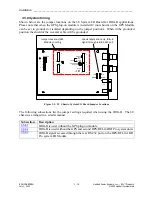
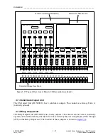
When the Relay Output Unit is installed in a Discrete I/O Base module, SW6 on the Relay Output
Unit corresponds to terminals 24 and 23 on the Discrete I/O Base module, SW5 on the Relay
Output Unit corresponds to terminals 22 and 21 on the Discrete I/O Base module, and so forth.
The same correlation exists when the unit is plugged onto a Comms I/O Base module. This is
shown pictorially in Figure 3-19.
SW1
SW2
SW3
SW4
SW5
SW6
K1
K2
K3
K4
K5
K6
A
B
A
A
A
B
B
B
B
B
A
A
Move jumpers from Form
A (normally open) to
Form B (normally closed)
F
O
R
M
A
F
O
R
M
B
S
W
1
Jumper Setting (typical)
Front of Chassis
Figure 3-18. Component side of Relay Output Unit (RF-500815)


