System Description ____________________________________________________________________
RF-MCGARDPRO
Hubbell Power Systems, Inc.
–
RFL™
Products
July 1, 2022
©2022 Hubbell Incorporated
2-14
2.6
Front Panel Indicators/Connections
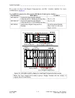
The only indicators present on the HPS/RFL GARD Pro system front panel are 20 programmable
tri-colored LEDs and a green power ON light. The LEDs are normally factory set but can be
customized by the user. The main user interface is through an Ethernet port for connection to a
web-based server.
Shown below is a typical HPS/RFL GARD Pro system LED configuration for a 3U chassis. Note
that in most applications not all the LEDs are used. A 6U chassis has the same configuration
however the LEDs are orientated vertically.
RESET
NET
PWR
2
Green indicates that power is
applied to the
RFL™ GARD
Pro™ System
Programmable reset
button will reset the
LED's as specified
LED assignments are
printed on a card and
inserted into a clear
plastic pocket attached
to the Front Panel
1.
3.
5.
7.
9.
11.
13.
15.
17.
19.
SYSTEM MAJOR ALARM
2.
TRIP KEY 1
4.
TRIP KEY 2
6.
TRIP RX 1
8.
TRIP RX 2
10.
GUARD RX
12.
14.
RX ALARM
16.
TX FAIL
18.
RPM ALARM
20.
SYSTEM MINOR ALARM
Each LED can have four color
states: Off, Green, Yellow and Red.
LED,s are shown active
4 6 8 10 12 14 16 18 20
1 3 5 7 9 11 13 15 17 19
RJ-45 Ethernet port for direct
connection to a laptop or PC
LED Indication: No illumination
– no connection
Left indicator, solid green
– connection made
Right indicator, flashing green
– data transfer
Figure 2-12. HPS/RFL GARD Pro System Front Panel, Indicators/Connections


