Digital Communications Interfaces ________________________________________________________
RF-MCGARDPRO
Hubbell Power Systems, Inc.
–
RFL™
Products
July 1, 2022
©2022 Hubbell Incorporated
7-20
7.3.4 Timeslot
– Bus settings Description
1
2
3
4
5
6
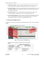
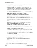
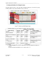
Figure 7-16. Digital Comms Configuration fields
The descriptions, of the settings below, describes Bus-1 tab settings, but the descriptions apply
to Bus 2 tab settings equally. All selections are done with a drop-down menu.
1.
Tab Title
– “TIMESLOT MAPPING > BUS 1”: This is the heading of this tab.
2.
Bus Master
: This setting is typically automatically configured by the GARD Pro based
on the rules described above. But, in some cases, it is may be configured by the user.
The default value for a bus master is the Comms interface module which occupies the
lowest # timeslot.
3.
Bus Timing
: This setting configures the timing parameter of the comms interface which
is programmed as the Bus Master.
The master timing can be Internal or Loop (recovered).
4.
Timeslot
: This is a read-only column to indicate the timeslot of the comms bus available
for configuration. There are always 12 timeslots, available on either Bus.
5.
Function
: This drop-down field is used to select a function to be mapped to the timeslot
in that row. You can select any of the following:
•
Installed TPS channels
•
Service Channel A
•
Service Channel B
•
Aux Channel
•
Idle
•
Not Used
6.
Comms Interface
: This drop-down field is used to select a comms interface which will
carry the function data of the timeslot in that row. You can select any installed Comms
Interfaces.


