Chapter 3
3-15
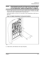
Installing the UPS
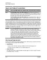
Input and Output Connections
Output wiring should be sized based on input current requirements of the load
equipment, in accordance with local codes.
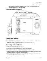
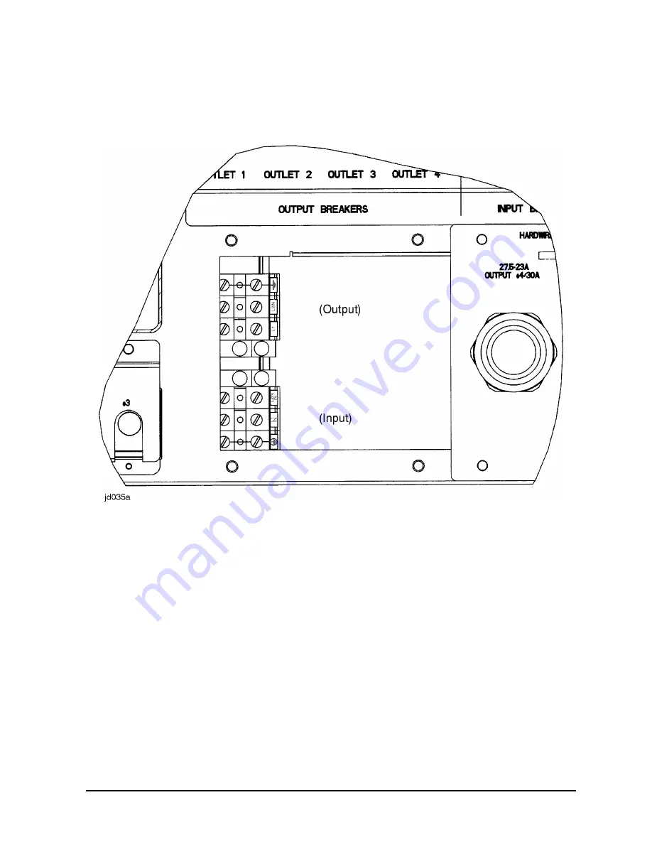
Figure 3-10 A3589A Terminal Block
Torque Specifications
Use a flat-bladed screwdriver to secure the screws to the terminal block. The following
torque specifications are required:
For Line and Ground Terminals: 10.6 - 12.3 in-lb (1.2 - 1.4 Nm)
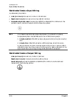
Removing the Access Panels
1. Turn off the AC input at the power source.
2. Make certain that the UPS/BATTERY switch is set to
DISABLE
.
3. Make certain that the Service Bypass switch is in the
NORMAL
position.
4. Loosen and remove the four screws that secure each access panel to the rear panel of
the Service Bypass Unit. Remove the access panels.
5. Feed the AC input and output wires through the right access panel to the left access
panel for connection to the terminal block.
Содержание PowerTrust A3589A
Страница 7: ...Contents Contents 5 ...
Страница 8: ...Contents 6 Contents ...
Страница 10: ...Contents 8 Figures ...
Страница 12: ...Contents 10 Tables ...
Страница 14: ...2 ...
Страница 20: ...Preface 8 ...
Страница 22: ...Preface 10 ...
Страница 52: ...1 30 Chapter1 Overview Specifications Figure 1 8 UPS Input Voltage Transfer Points ...
Страница 56: ...1 34 Chapter1 Overview UPS Modes Figure 1 10 Simplified UPS 5 5 kVA UPS Block Diagram ...
Страница 62: ...1 40 Chapter1 Overview Support Information ...
Страница 76: ...2 14 Chapter2 Unpacking and Inspecting Shipping and Storage Requirements ...
Страница 104: ...3 28 Chapter3 Installing the UPS Examples of PowerTrust Connections in a System ...
Страница 116: ...5 4 Chapter5 Verification Procedures Load Testing ...
Страница 148: ...7 6 Chapter7 Cleaning and Maintenance Exchanging Batteries Fan ...
Страница 190: ...A 42 AppendixA HP UX UPS Monitor Error Messages Log Only Messages ...
Страница 218: ...C 8 AppendixC Configuring the OS for the PowerTrust UPS Power Failing the UPS ...

