6-6
Chapter 6
Troubleshooting
Alarm Indicators
Alarm Indicators
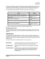
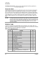
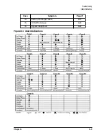
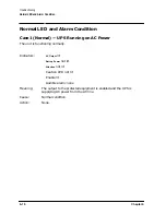
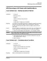
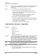
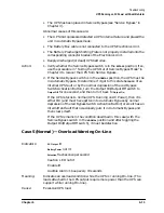
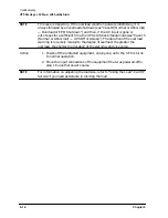
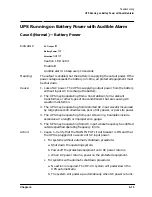
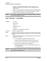
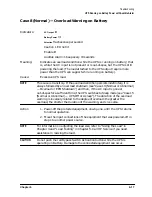
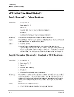
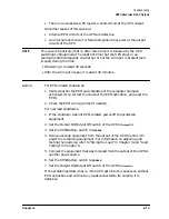
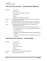
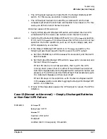
Interpreting indicators and audible alarms and suggested actions are included in the case
descriptions. Figure 6-1 shows the possible indicator light combinations and relates each to
a case number.
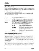
Front Panel Visible Indicators (LEDs)
The following three indicator lights (LEDs) are located on the front control panel of the
Electronics Unit as shown in Figure 1-2.
Rear Panel Visible Indicators (LEDs)
Rear Panel Enable LED
The Enable LED is on the rear panel of the UPS (see item
13
in Figure 1-3). This green
light indicates that the UPS is enabled and operating (sensing the input AC power). The
Enable light is normally on if the UPS/BATTERY switch is on
ENABLE
. However, there is
one exception: If the batteries discharge while AC input power is off, and the AC Output
On/Output Off switch is set to
Output On
, the Enable light turns off. It remains off until AC
input power returns.
Caution LED
The UPS has a Caution LED on the rear panel (see item
17
in Figure 1-3). This amber light
indicates whether it is safe to change the position of the Bypass switch—from Bypass to
Normal or from Normal to Bypass—without affecting the AC output to the load. If the
AC Output
A green light indicates that power is being supplied to the output
receptacles of the Service Bypass Unit.
Battery Power
A yellow light indicates that the unit is supplying power from its battery.
It may also light momentarily when the UPS is adjusting to a change in
input voltage. Caution: Do not push the red button while the UPS is
operating on battery. Damage to the connected equipment can occur.
Attention
A yellow light indicates that the unit needs attention. It may flash with
one or two flashes or remain on continuously. This indicator, in
conjunction with the audible alarm, has multiple meanings.
One flash
a flash every second indicates an overload
condition.
Two flashes
two quick flashes every 10 seconds along with
the 3-beep audible alarm indicates an
overtemperature condition.
Light on
continuously
indicates a condition that needs your attention,
such as a system failure.
Содержание PowerTrust A3589A
Страница 7: ...Contents Contents 5 ...
Страница 8: ...Contents 6 Contents ...
Страница 10: ...Contents 8 Figures ...
Страница 12: ...Contents 10 Tables ...
Страница 14: ...2 ...
Страница 20: ...Preface 8 ...
Страница 22: ...Preface 10 ...
Страница 52: ...1 30 Chapter1 Overview Specifications Figure 1 8 UPS Input Voltage Transfer Points ...
Страница 56: ...1 34 Chapter1 Overview UPS Modes Figure 1 10 Simplified UPS 5 5 kVA UPS Block Diagram ...
Страница 62: ...1 40 Chapter1 Overview Support Information ...
Страница 76: ...2 14 Chapter2 Unpacking and Inspecting Shipping and Storage Requirements ...
Страница 104: ...3 28 Chapter3 Installing the UPS Examples of PowerTrust Connections in a System ...
Страница 116: ...5 4 Chapter5 Verification Procedures Load Testing ...
Страница 148: ...7 6 Chapter7 Cleaning and Maintenance Exchanging Batteries Fan ...
Страница 190: ...A 42 AppendixA HP UX UPS Monitor Error Messages Log Only Messages ...
Страница 218: ...C 8 AppendixC Configuring the OS for the PowerTrust UPS Power Failing the UPS ...

