


Appendix D
D-21
Field Replaceable Units
Removal and Replacement Procedures
CAUTION
If the yellow caution light is flashing, do not proceed. Switching the UPS into
Bypass mode when the caution light is flashing may disrupt power to the
load. Call HP Service. If the yellow caution light is not flashing, continue.
2. While depressing the red button on the Service Bypass Unit, set the Service Bypass
switch to
Bypass
.
A continuous alarm will sound indicating that the UPS is in Bypass mode.
3. Set the rear panel UPS/BATTERY switch to
DISABLE
. The alarm will turn off.
4. Use a screwdriver to loosen the screw at the center of each captive thumbscrew on the
Battery Precharge Shorting Plate, then unscrew the thumbscrews and remove the
plate. See Figure 3-8.
5. Disconnect the Battery Box cable from the Electronics Unit.
6. Remove the bezel assembly and the four Torx screws that secure the Electronics Unit to
the rack.
7. Remove the old panel assembly by removing the four Torx screws that hold it to the
front of the Electronics Unit.
8. Disconnect the cable from the circuit board by grasping the red connector and gently
pulling it out from the 10-pin right-angle header on the side of the circuit board.
9. Install the replacement control panel.
a. Connect the cable to the circuit board. Refer to Figure D-6.
The number on the connector must match the number on the board.
Connect the cable to the circuit board by plugging the cable connector into the 10-pin
right-angle header on the side of the circuit board.
Be careful not to bend or break any of the header pins.
b. Attach the control panel to the front panel.
i. Align the holes in the housing flanges with the holes in the front panel of the
UPS. Secure with the four screws provided in the kit.
ii. Remove the protective clear plastic film that covers the label.
Содержание PowerTrust A3589A
Страница 7: ...Contents Contents 5 ...
Страница 8: ...Contents 6 Contents ...
Страница 10: ...Contents 8 Figures ...
Страница 12: ...Contents 10 Tables ...
Страница 14: ...2 ...
Страница 20: ...Preface 8 ...
Страница 22: ...Preface 10 ...
Страница 52: ...1 30 Chapter1 Overview Specifications Figure 1 8 UPS Input Voltage Transfer Points ...
Страница 56: ...1 34 Chapter1 Overview UPS Modes Figure 1 10 Simplified UPS 5 5 kVA UPS Block Diagram ...
Страница 62: ...1 40 Chapter1 Overview Support Information ...
Страница 76: ...2 14 Chapter2 Unpacking and Inspecting Shipping and Storage Requirements ...
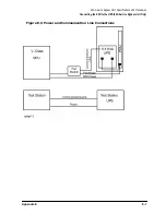
Страница 104: ...3 28 Chapter3 Installing the UPS Examples of PowerTrust Connections in a System ...
Страница 116: ...5 4 Chapter5 Verification Procedures Load Testing ...
Страница 148: ...7 6 Chapter7 Cleaning and Maintenance Exchanging Batteries Fan ...
Страница 190: ...A 42 AppendixA HP UX UPS Monitor Error Messages Log Only Messages ...
Страница 218: ...C 8 AppendixC Configuring the OS for the PowerTrust UPS Power Failing the UPS ...