background image

A-22

Appendix A

HP-UX UPS Monitor Error Messages

Log-Only Messages

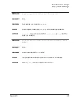
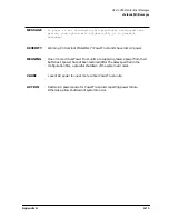
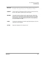
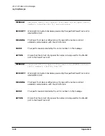
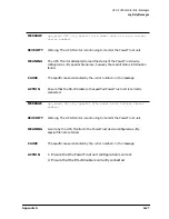
MESSAGE

ups_mond: upstty <tty special file name> failed open: <error

number>; ignoring that tty and continuing

SEVERITY

Warning/Error. System hardware powered by the specified PowerTrust unit is
UNPROTECTED.

MEANING

The PowerTrust device configured as <tty special file name> could not
establish communication with the UPS Monitor.

CAUSE

The specific cause is denoted by the <error number> in the message.

ACTION

Ensure that the correct <tty special file name> is being used for the RS-232
port to the PowerTrust unit.

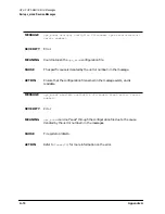
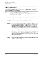
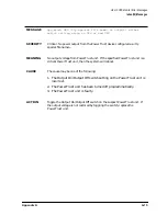
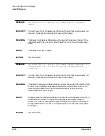
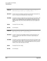
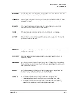
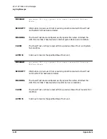
MESSAGE

ups_mond: UPS <tty special file name> ioctl(TCGETA) failed:

<error number>; ignoring that UPS

SEVERITY

Warning/Error. System hardware powered by the specified PowerTrust unit is
UNPROTECTED.

MEANING

The PowerTrust device configured as <tty special file name> could not
establish communication with the UPS Monitor.

CAUSE

The specific cause is denoted by the <error number> in the message.

ACTION

Ensure that the correct <tty special file name> is being used for the RS-232
port to the PowerTrust unit.

Содержание PowerTrust A3589A

Страница 1: ...PowerTrust System Guide HP Model A3589A 5 5 kVA Rack Mounted UPS Part No A3329 90002 Edition 3 December 1997 E1297 Printed in USA ...

Страница 2: ...nment is subject to restrictions as set forth in subparagraph c 1 ii of the Rights in Technical Data and Computer Software clause at DFARS 252 227 7013 for DOD agencies and subparagraphs c 1 and c 2 of the Commercial Computer Software Restricted Rights clause at FAR 52 227 19 for other agencies HEWLETT PACKARD COMPANY 3000 Hanover Street Palo Alto California 94304 U S A Copyright Notices copyright...

Страница 3: ...1 32 Automatic Bypass Mode 1 32 Service Bypass Mode 1 33 Sleep Mode 1 35 UPS Safety Preparedness 1 36 Safety Information 1 36 Handling Emergencies 1 36 Hazardous Product Information 1 37 Suggested Hazardous Product Procedures 1 37 Support Information 1 39 Support Strategy 1 39 Training 1 39 Battery Type 1 39 2 Unpacking and Inspecting Receiving the PowerTrust UPS 2 2 Physical Inventory 2 2 Unpacki...

Страница 4: ...nsion Cabinet System Field Integrated 3 20 Example 2 Single Expansion Cabinet System Factory Integrated 3 22 Example 3 Dual Expansion Cabinet System Field Integrated 3 24 Example 4 Dual Expansion Cabinet System Factory Integrated 3 26 4 Power On Power Off Procedures Power On Procedures 4 2 Initial Power On or Power On After Shutdown 4 2 Powering On the UPS After Being Powered Off for a Short Time ...

Страница 5: ...Battery 6 17 UPS Halted Has No AC Output 6 18 Case 9 Abnormal Failure Shutdown 6 18 Case 10 Normal or Abnormal Overload or EPO Shutdown 6 18 Case 11 Normal Abnormal Overtemperature Shutdown 6 20 Case 12 Normal or Abnormal Output Disabled 6 20 Case 13 Normal or Abnormal Deeply Discharged Batteries or Non Fatal UPS Failure 6 21 Case 14 Abnormal Battery Precharge Failure 6 22 Case 15 Normal or Abnorm...

Страница 6: ...lacing Battery Packs D 6 Removing and Replacing the Battery Box D 9 Removing and Replacing the Service Bypass Unit D 11 Removing and Replacing Hardwire Conversion Kit 30A Service Bypass Unit Only D 13 Removing and Replacing North American Conversion Kit D 17 Removing and Replacing Control Panel and Label Kit D 19 Removing and Replacing the Electronics Unit Fan Assembly D 24 E 40A Service Bypass Un...

Страница 7: ...Contents Contents 5 ...

Страница 8: ...Contents 6 Contents ...

Страница 9: ...Locations 3 5 Figure 3 3 Inserting a Battery Pack into the Battery Box 3 6 Figure 3 4 Rail and Clip Nut Locations for Rackmounting the Electronics Unit 3 7 Figure 3 5 Clip Nut Locations for Rackmounting the Service Bypass Unit 3 8 Figure 3 6 Attaching the Front Bezel to the Electronics Unit 3 10 Figure 3 7 PDU Ground Connection 3 11 Figure 3 8 Battery Precharge Shorting Plate 3 12 Figure 3 9 Reatt...

Страница 10: ...Contents 8 Figures ...

Страница 11: ...formation 1 4 Table 1 2 A3589A Specifications 1 24 Table 3 1 Example of Determining Load 3 2 Table 6 1 Troubleshooting Cases 6 8 Table 7 1 Manufacturing Month Codes 7 5 Table D 1 Replaceable Parts List D 2 Table D 2 UPS Serial Communications Cables D 3 ...

Страница 12: ...Contents 10 Tables ...

Страница 13: ...7 Third Edition December 1997 NOTE Reader Comments We welcome your comments about our documentation If you have editorial suggestions or recommended improvements for this document please write to us You can reach us through e mail at hardwaredocs cup hp com or by sending your letter to Documentation Manager M S 5657 Hewlett Packard Company 8000 Foothills Blvd Roseville CA 95747 6588 USA Please inc...

Страница 14: ...2 ...

Страница 15: ...l the indicated conditions are fully understood and met CAUTION The CAUTION sign denotes a hazard It calls attention to an operating procedure practice or the like which if not done correctly or adhered to could damage or destroy part or all of the product Do not proceed beyond a CAUTION sign until the indicated conditions are fully understood and met Please read all safety considerations carefull...

Страница 16: ...d to a circuit provided with 63 amperes maximum branch circuit overcurrent protection in accordance with local codes CAUTION Do not place magnetic media on the UPS Avoid plugging the unit into a wall outlet controlled by a switch If the outlet is controlled by a switch cover or protect the switch from being turned off accidentally The switch will not turn off the PowerTrust UPS instead the PowerTr...

Страница 17: ...ment in a residential area is likely to cause harmful interference in which case the user will be required to correct the interference at his own expense EMI Statement Canada Only This Class A digital apparatus meets all requirements of the Canadian Interference Causing Equipment Regulations Japanese Radio Frequency Interference Japanese VCCI Radio Frequency Notice EMI Statement European Union War...

Страница 18: ...ow the unit to become enabled without the operator s knowledge A battery can present a risk of electrical shock and or burn from high short circuit current Observe proper precautions Both the Mains and Bypass circuit breakers are the Mains disconnect when the Service Bypass switch is in the NORMAL position The facility branch circuit is the Mains disconnect when the Service Bypass switch is in the...

Страница 19: ...ystem WARNING This product has not been evaluated for connection to an IT power system an AC distribution system having no direct connection to earth according to IEC 950 EN50091 1 Leakage Current WARNING To reduce the risk of electric shock never operate this product with the input or output ground conductors disconnected An earth connection is essential before connecting the supply Due to the ty...

Страница 20: ...Preface 8 ...

Страница 21: ...uptible Power Supply UPS WARNING Some of the procedures described in this manual present the risk of serious physical injury and or damage to the PowerTrust UPS They should be performed by trained service personnel only See Table 1 1 Other Reference Documents HP 3000 Configuring Systems for Terminals Printers and other Serial Devices HP UX System Administration Task Manual ...

Страница 22: ...Preface 10 ...

Страница 23: ... 5 kVA UPS Information about this book Terms used in this manual Power failure operation Electronics Unit and Bypass operations Control Panel switches and indicators PowerTrust UPS rear panel Battery Box Service Bypass Unit Specifications UPS safety preparedness Support information ...

Страница 24: ...e Each PowerTrust UPS can be ordered in a factory integrated expansion cabinet as part of a supported HP 3000 or HP 9000 computer system order or as a field installable upgrade to an existing HP 3000 or HP 9000 system The entire unit is designed to be installed at the bottom of the Hewlett Packard A1883A A1884A A1896A or A1897A expansion cabinet 19 inch rack for any supported system A UPS compatib...

Страница 25: ...Chapter 1 1 3 Overview Introduction Figure 1 1 Rack mounted PowerTrust 5 5 kVA UPS This UPS provides 5 5 kVA of power protection for approximately 15 minutes ...

Страница 26: ... equipment if they attempt to perform some of the operations described in this manual Description Operator Information Service Information Chapter 1 Overview X X Chapter 2 Unpacking and Inspecting X Chapter 3 Installing the UPS X Chapter 4 Power On Power Off Procedures X X Chapter 5 Verification Procedures X Chapter 6 Troubleshooting X X Chapter 7 Cleaning and Maintenance X Appendix A HP UX UPS Mo...

Страница 27: ...ctronic components of the PowerTrust UPS front panel The front panel of the Electronics Unit Also called the control panel hold up time The amount of time that the UPS will maintain AC power to the connected equipment after the external AC power has failed or been removed This is about 15 minutes when the batteries within the UPS are fully charged and the unit is powering its rated load If the UPS...

Страница 28: ...The UPS must be in Service Bypass mode by switching the Service Bypass switch to BYPASS when its Electronics Unit or Battery Box needs to be serviced or replaced Loss of input power while the UPS is in this mode results in a complete loss of power to the connected equipment For more information refer to UPS Modes Sleep mode The state of the UPS after prolonged disruptions in AC input power or afte...

Страница 29: ...efined voltage AC power rises above a predefined voltage The following actions should be taken after the UPS detects an AC power failure and sounds an alarm 1 Shut down the operating system 2 Power down the protected equipment 3 Switch the UPS Output On Output Off switch to Output Off Refer to Figure 1 3 4 If the power will be off for an extended time perform the following steps otherwise proceed ...

Страница 30: ...quipment To enter Service Bypass mode the red Bypass button must be pressed and the Service Bypass switch must be manually set to BYPASS In Service Bypass mode the AC input bypasses the Electronics Unit and is sent directly to the output receptacles WARNING The Electronics Unit must be serviced only while the UPS is in Service Bypass mode Replacement of the Electronics Unit with the UPS in Automat...

Страница 31: ...rol Panel Switches and Indicators The PowerTrust Electronics Unit has a user accessible control panel on its front as shown in Figure 1 2 Descriptions of the switches and indicators on the control panel follow the illustration Figure 1 2 PowerTrust UPS Control Panel ...

Страница 32: ...hapter 6 Troubleshooting 4 Silence Alarm Test A pushbutton switch Pressing this switch silences the alarm if the audible alarm is active The Attention and or Battery Power lights remain lit however Pressing this switch again reactivates the audible alarm If the audible alarm is not active and the UPS Electronics Unit has not failed pushing this button causes the UPS to switch to battery operation ...

Страница 33: ...ix E 40A Service Bypass Unit Specifications and Procedures 2 IEC Output Receptacles Three IEC320 C19 output receptacles are available on both North American and worldwide versions of the PowerTrust UPS Up to three expansion cabinet Power Distribution Units PDUs can be plugged in here 3 NEMA Output One NEMA L6 30R output receptacle North American version only An SPU peripheral or PDU in an adjacent...

Страница 34: ...ill not be supported 4 Access Plate This plate provides access to the terminal block where hardwired connections can be made 5 EPO Terminals A pair of screw terminals is provided for connection to an Emergency Power Off EPO system For normal operation these terminals must be connected by a jumper or by the EPO system Removing the connection causes the UPS AC output to shut down The output remains ...

Страница 35: ...ming out of the corresponding output receptacle remains off until the cause of the overcurrent is corrected the circuit breaker is reset and depending on the severity of the problem the UPS BATTERY switch is cycled turned off then back on This restores the UPS to normal operation Figure 1 3 shows the AC power input for the 30A Service Bypass Unit For information on the 40A Service Bypass Unit refe...

Страница 36: ...r to the protected equipment you should always check that the BYPASS INPUT circuit breaker is ON before pressing this button 11 Service Bypass Switch This rotary switch allows you to isolate and disconnect the AC input from the Electronics Unit and batteries so that these components can be serviced without disrupting power to the connected equipment This switch is also used to manually override au...

Страница 37: ...matic bypass condition 13 Enable Light This green light indicates that the UPS is enabled and operating The Enable light is normally on if the UPS BATTERY switch is set to ENABLE However there are two exceptions 1 If the UPS BATTERY switch is set to the ENABLE position while the AC input power is off the Enable light flashes and then remains off until AC input power returns 2 If the batteries disc...

Страница 38: ...cess panel for making a hardwired output connection in a manner appropriate to local electrical codes Hardwired output is not available with 40A Service Bypass Units 2 IEC Output Receptacles Three IEC320 C19 output receptacles are available on both North American and worldwide versions of the PowerTrust UPS Up to three expansion cabinet Power Distribution Units PDUs can be plugged in here 3 AC Pow...

Страница 39: ...erminal block where hardwired connections can be made For information about the Access Plate on the 40A Service Bypass Unit refer to Appendix E 40A Service Bypass Unit Specifications and Procedures 5 EPO Terminals A pair of screw terminals is provided for connection to an Emergency Power Off EPO system For normal operation these terminals must be connected by a jumper or by the EPO system Removing...

Страница 40: ...output receptacle see 3 in Figure 1 4 The AC coming out of the corresponding output receptacle remains off until the cause of the overcurrent is corrected the circuit breaker is reset and depending on the severity of the problem the UPS BATTERY switch is cycled turned off then back on This restores the UPS to normal operation For information on the 40A Service Bypass Unit refer to Appendix E 40A S...

Страница 41: ...er to the protected equipment you should always check that the BYPASS INPUT circuit breaker is ON before pressing this button 11 Service Bypass Switch This rotary switch allows you to isolate and disconnect the AC input from the Electronics Unit and batteries so that these components can be serviced without disrupting power to the connected equipment This switch is also used to manually override a...

Страница 42: ...atic bypass condition 13 Enable Light This green light indicates that the UPS is enabled and operating The Enable light is normally on if the UPS BATTERY switch is set to ENABLE However there are two exceptions 1 If the UPS BATTERY switch is set to the ENABLE position while the AC input power is off the Enable light flashes and then remains off until AC input power returns 2 If the batteries disch...

Страница 43: ...Chapter 1 1 21 Overview Battery Box Battery Box Each UPS includes a Battery Box that contains ten replaceable battery packs Figure 1 5 PowerTrust UPS Battery Box ...

Страница 44: ... 7 shows the North American and Worldwide versions of the Service Bypass Unit respectively Figure 1 6 shows the 30A Service Bypass Unit The 40A Service Bypass Unit has some differences For information on the 40A unit refer to Appendix E 40A Service Bypass Unit Specifications and Procedures Figure 1 6 PowerTrust UPS Service Bypass Unit 30A North American Version ...

Страница 45: ...Chapter 1 1 23 Overview Service Bypass Unit Figure 1 7 PowerTrust UPS Service Bypass Unit 30A Worldwide Version ...

Страница 46: ... Hz 2 Normal Operating Voltage Range 180 256 VAC AC Line Input Transfer Points On line to On battery Normal to Overvoltage 262 272 VAC Normal to Undervoltage 162 168 VAC Normal to Underfrequency For 50 Hz operation below 46 5 Hz For 60 Hz operation below 56 5 Hz Normal to Overfrequency For 50 Hz operation below 53 5 Hz For 60 Hz operation below 63 5 Hz On battery to On line Overvoltage to Normal 2...

Страница 47: ...ncy 3 On battery 50 3 Hz or 60 3 Hz 4 Auto or Service Bypass Same as the AC line input Rated Output volt amperes VA On line 5 5500 VA continuous On battery5 5500 VA until fully discharged Auto or Service Bypass 6 5500 VA continuous Rated Power On Line 7 5500 W continuous On battery7 5500 W until fully discharged Auto or Service Bypass6 5500 VA continuous Output Waveshape On line Matches the input ...

Страница 48: ... or 40A Battery Type Maintenance free sealed lead acid Nominal voltage 48 VDC Runtime 25 C or above 15 min over battery lifetime Runtime new battery 15 min 5 C to 40 C at 0 3000 m Charging Time 25 C 14 5 hours Lifetime Approximately 4 years Environmental Specifications Operating Limits Temperature 10 5 to 40 C10 up to maximum operating altitude Recommended Temperature10 20 to 25 C10 Humidity 15 to...

Страница 49: ...80kg 396 lbs Weight without batteries 30kg 66 lbs Physical Specifications Battery Pack Dimensions packaged Height 39 37cm 15 50in Width 23 18cm 9 13in Length 50 80cm 20 00in Weight 18 18kg 40 lbs Dimensions unpackaged Height 25 88cm 10 19in Width 8 0cm 3 15in Length 37 47cm 14 75in Weight 15kg 33 lbs Physical Specifications Service Bypass Unit 30A Dimensions packaged Height 33 02 cm 13 00 in Width...

Страница 50: ...eady on Frequency range specified above 3 For input frequencies within the range specified in Normal Operating Fre quency Range 4 The first number applies when the UPS operates within 50 3 Hz before the input power fails or violates the operating limits The second number applies when the UPS operates within 60 3 Hz before the input power fails or violates the operating limits 5 For loads with cres...

Страница 51: ...connectors The UPS should power on only when the input AC is between 175 V and 264 V 50 60 Hz Other voltage information is shown in the following table While running on line the output voltage can be from 200 VAC to 244 VAC While on battery the output voltage must be 230 VAC with the output voltage regulated to within 3 Thus the on battery output voltage is always in the range of 234 VAC and 223 V...

Страница 52: ...1 30 Chapter1 Overview Specifications Figure 1 8 UPS Input Voltage Transfer Points ...

Страница 53: ...imum operating frequency or above the maximum operating frequency for either 50 Hz or 60 Hz operation when the UPS is first turned on power will not be applied to the AC output The minimum and maximum frequency ranges in Hz are specified in Table 1 2 Other key points regarding frequency The UPS has no switches or jumpers to set input or output frequency The unit is auto ranging that is it configur...

Страница 54: ...h is set to NORMAL and on to the output receptacles This mode is used to allow time to safely shutdown the SPU or other loads Fully charged batteries can sustain power to the SPU and other connected equipment for up to 15 minutes CAUTION Do not push the red button while the UPS is operating on battery Damage to the connected equipment can occur Automatic Bypass Mode When the Electronics Unit detec...

Страница 55: ...Service Bypass mode occurs when the Service Bypass switch is manually turned to BYPASS In Service Bypass mode AC input power passes through the Bypass breaker through the Service Bypass switch which is set to BYPASS and on to the output breakers and receptacles Because the Electronics Unit and Battery Box are isolated from the AC input and the output there is no power failure protection while in t...

Страница 56: ...1 34 Chapter1 Overview UPS Modes Figure 1 10 Simplified UPS 5 5 kVA UPS Block Diagram ...

Страница 57: ...down Improperly installed UPS Battery Box cable not properly connected or Battery Precharge Shorting Plate not properly installed Certain internal UPS faults In addition the UPS also goes into Sleep Mode after it has been in Automatic or Service Bypass for more than 30 minutes both of these cases are called Bypass Sleep Mode to distinguish them from all the other cases In either Automatic or Servi...

Страница 58: ...l flame or smoke momentarily emitting from the UPS Safety Information Safety information you should know to avoid hazards Obtain proper training before servicing any UPS product Remember unless properly shut down all UPS outlet receptacles remain live even after the UPS is unplugged Follow the published service procedures exactly deviations may stress components Refer to the handbook Electrical Sa...

Страница 59: ... you are uncertain about how to proceed Hazardous Product Information Suggested Hazardous Product Procedures Hazardous Components Percent Sulfuric Acid H2SO4 10 20 Concentration of H2SO4 exists depending on state of discharge Lead Pb 30 60 Lead Dioxide PbO2 5 25 Lead Sulfate PbSO4 1 25 Pb exists either in the form of Pb PbO2 or PbSO4 depending on state of discharge Situation Procedure Extinguishin...

Страница 60: ...anical shock Handling released or spilled material If a battery is accidentally broken and electrolyte sulfuric acid leaks out put on waterproof gloves and wipe it up with a cloth Neutralize the acid with some alkaline substance such as ammonia solution or baking soda sodium bicarbonate Contacting battery acid Wash eyes and skin with water immediately after any contact with battery acid Disposing ...

Страница 61: ...ed lead acid The batteries should be recharged periodically when they are stored The frequency of the recharge depends on the storage temperature See Shipping and Storage Requirements in Chapter 2 Even when kept charged a battery pack s hold up time will decrease over the life of the pack Each battery pack must be replaced every 3 to 5 years to maintain the 15 minute run time If the UPS is exposed...

Страница 62: ...1 40 Chapter1 Overview Support Information ...

Страница 63: ...ping and storage requirements WARNING The following procedures as well as all other service cleaning and maintenance of the UPS should be performed only by qualified service trained Hewlett Packard personnel You should understand all WARNINGs and CAUTIONs located in the front matter before proceeding with the installation and operation of the PowerTrust UPS ...

Страница 64: ...r If you observe any damage refer to Claims Procedures later in this chapter Physical Inventory Open the shipping container and find the packing list that lists the equipment supplied Compare the product and option numbers on the packing list with the purchase order to verify that the shipment is correct If any of the equipment is damaged or missing refer to Claims Procedures later in this chapter...

Страница 65: ...arton contains the Service Bypass Unit See Figure 2 1 The shipment will also include a separate carton containing the Power Distribution Unit PDU if one was ordered Figure 2 1 A3589A PowerTrust UPS Packaging The shipping carton for the Battery Box and Electronics Unit consists of an inverted half carton which covers the top of the unit and a tray like bottom on which the unit sits Figure 2 3 and F...

Страница 66: ... are under tension Be careful when cutting the shipping straps to prevent personal injury Carefully cut and remove the straps that secure the cartons to the shipping pallet Unpacking the Service Bypass Unit Use the following procedure to unpack the Service Bypass Unit 1 Remove the carton containing the Service Bypass Unit top box 2 Open the carton and remove the AC power cord Figure 2 2 shows how ...

Страница 67: ...it and set them aside 4 Remove the packing material on which the power cord was resting 5 Remove the L shaped corrugated cardboard pads from the top of the Service Bypass Unit 6 Check the packing material for signs of damage which could indicate rough handling during transit Refer to Claims Procedures later in this chapter if you discover any damage 7 Carefully remove the Service Bypass Unit ...

Страница 68: ...let open it 2 Remove the packing material from the top and sides of the Battery Box See Figure 2 3 3 Check the packing material for signs of damage Refer to Claims Procedures later in this chapter if you discover any damage 4 Remove the top half carton item 1 from the tray like bottom of the shipping carton 5 Before lifting the Battery Box out of its shipping carton follow the step by step instruc...

Страница 69: ...nel only WARNING Batteries can present a risk of electrical shock and or burn from high short circuit current Observe proper precautions Do not stack batteries on top of each other Do not allow anything to touch the battery terminals Do not pierce battery pack wiring insulation Do not allow conductive tools or jewelry to touch battery packs or battery terminals 1 Loosen the thumbscrew at the botto...

Страница 70: ...ous voltages Do not short connectors together Do not stack battery packs on top of each other doing so may damage them or cause physical injury Figure 2 5 Removing a Battery Pack from the Battery Box 5 Repeat steps 2 through 4 until all of the batteries have been removed from one side 6 Repeat steps 1 through 4 for the batteries on the other side of the Battery Box When you have finished you shoul...

Страница 71: ...ure 2 6 while removing the Electronics Unit from its shipping carton 1 Remove the piece of plywood located on the top of the carton containing the Electronics Unit 2 Open the carton containing the Electronics Unit 3 Remove the packing material from around the Electronics Unit 4 Remove the top half carton item 1 from the tray like bottom of the shipping carton 5 Remove any additional material such ...

Страница 72: ... Also look for damage such as broken controls and connectors dented corners scratches bent panels and loose components Refer to Claims Procedures later in this chapter if you discover any damage 7 Along with one other person get a firm grip on all four lifting straps and lift the Electronics Unit straight up and out of the shipping carton and set it aside ...

Страница 73: ...g materials for inspection Repacking If the PowerTrust UPS must be reshipped use the original shipping and packing materials if available and undamaged If unavailable contact the local Hewlett Packard Sales and Service Office for repacking information and materials Do not reuse damaged packing material or return the unit without the proper packaging materials Returning PowerTrust Battery Packs Def...

Страница 74: ...ck depends on the temperature of the storage area The charge on a battery should not be allowed to drop below 50 Figure 2 7 shows how long a battery pack takes to reach a 50 charge at 40 C 104 F 30 C 88 F and 25 C 77 F Figure 2 8 shows the time for the battery capacity to decrease to 50 over temperatures ranging from 18 C 64 to about 54 C 129 F For example if a battery pack has been stored at 20 C...

Страница 75: ...o 90 non condensing at 65 C Altitude 4 572 meters 15 000 feet The batteries must be recharged periodically depending on the storage temperature CAUTION Storing battery packs without recharging periodically will cause damage to the battery packs resulting in reduced run time The PowerTrust UPS should be protected from environmental extremes that can cause condensation within the unit ...

Страница 76: ...2 14 Chapter2 Unpacking and Inspecting Shipping and Storage Requirements ...

Страница 77: ...g the load Rackmounting procedures Hardwired connections Cabling connections Examples of PowerTrust connections in a system WARNING The following procedures as well as all other service cleaning and maintenance of the UPS should be performed only by qualified service trained Hewlett Packard personnel ...

Страница 78: ...y 1 4 c If no wattage number is given on the component multiply the volts by the amperage of the component 2 Sum all of the Volt Amperes VA of all the components to ensure that the total power required is less than or equal to the Volt Ampere VA rating of the UPS If more than the UPS VA rating is consumed in the cabinet additional PowerTrust UPS units will be required to provide power protection f...

Страница 79: ...lled by the factory Factory installation is optional 6 Connect the UPS to AC input power The details of these installation procedures are described in the sections that follow Installing the Battery Box The Battery Box contains ten battery packs For purposes of shipping the battery packs are included in the Battery Box When fully loaded a Battery Box weighs about 180 kg 396 lb and each battery pac...

Страница 80: ...re the Battery Box Two clip nuts should be placed on each cabinet side rail one in the 6th hole and one in the 13th hole up from the bottom of the cabinet side rail Figure 3 1 Rail Locations for the Battery Box 4 With the help of one other person slide the Battery Box onto the rackmount rails from the rear of the expansion cabinet so that the opening containing the battery cable is at the back of ...

Страница 81: ...ry packs one at a time moving from left to right a Slip the guide at the bottom of the new battery pack between the tracks at the bottom of the Battery Box and push the battery completely into the Battery Box slot See Figure 3 3 You may need to rock the battery pack up and down slightly to get it to slide on the track b Fasten the thumbscrew at the bottom of the battery pack ...

Страница 82: ...ails just above the Battery Box Four clip nuts are needed and should be placed in the 24th hole up from the bottom of each cabinet side frame rail 2 Four clip nuts are needed to secure the Electronics Unit From the front of the cabinet place two clip nuts in each front cabinet rail one in the 32nd hole and one in the 41st hole up from the bottom of the rail See Figure 3 4 ...

Страница 83: ...rackmount position from the front of the expansion cabinet just above the Battery Box As you slide the Electronics Unit into the cabinet fold the second set of straps over the top of the Electronics Unit and out of the way WARNING The Electronics Unit weighs about 68 kg 150 lbs It requires two people to move it Use all four lifting straps to lift the Electronics Unit 4 Secure the Electronics Unit ...

Страница 84: ...nuts one per side at the 32nd hole up from the bottom of the cabinet frame rail See Figure 3 5 b Two clip nuts one per side at the 41st hole up from the bottom of the frame rail There should be eight empty holes between each set of clip nuts Figure 3 5 Clip Nut Locations for Rackmounting the Service Bypass Unit 2 Make sure the Service Bypass switch is set to NORMAL and that the circuit breakers ar...

Страница 85: ...ervice Bypass Unit aside You will attach it after you plug in the output receptacles Attaching Front Bezel 1 Attach one bracket to each of the four front corners of the Electronics Unit and secure it with a single M4 7 Torx screw The alignment pins on each bracket must line up with small holes in the front panel See Figure 3 6 2 Position the front bezel onto the brackets so that the pins behind th...

Страница 86: ...less Power Distribution Unit PDU For field upgrades a switchless Power Distribution Unit PDU should have been ordered along with the UPS It should be installed next to the existing PDU in the expansion cabinet Tools required for installing the PDU 25 Torx driver 1 Loosen and remove the two screws that secure the existing PDU to the brackets attached to the cabinet frame 2 Loosen and remove the two...

Страница 87: ...This ground wire is required for safe operation of the unit Figure 3 7 PDU Ground Connection Connecting the Battery Box Cable to the Electronics Unit Use the following procedure to connect the cable from the Battery Box to the Electronics Unit 1 Before you begin make sure the UPS BATTERY switch is set to DISABLE 2 Locate the Battery Precharge Shorting Plate that covers the battery cable connector ...

Страница 88: ...thumbscrews on either side of the plate and remove it 4 From the Battery Box remove the plastic cover marked REMOVE FOR ASSEMBLY and dispose of it 5 Remove the Battery Box cable 6 Attach the Battery Box cable connector to the connector on the Electronics Unit After you attach the cable the capacitors will precharge 7 Check the Precharge Failure LED see Figure 1 3 If the LED is off continue ...

Страница 89: ...ter 6 8 Orient the plate so that the notch on the plate is positioned over the Battery Box cable connector then reattach the plate making sure that the prongs on the plate are pressed firmly into the clips in the Electronics Unit See Figure 3 9 Attaching the plate is not trivial You may need to rock the plate back and forth as you push it in Figure 3 9 Reattaching Battery Precharge Shorting Plate ...

Страница 90: ...version is prewired at the factory with an input line cord terminated with an 6 50P plug and an L6 30R output receptacle no hardwiring is required CAUTION It is recommended that you do not place intervening power conditioning equipment between the PowerTrust UPS and the AC mains power source Such power conditioning equipment might interact with the PowerTrust UPS or the connected load causing faul...

Страница 91: ...ions are required For Line and Ground Terminals 10 6 12 3 in lb 1 2 1 4 Nm Removing the Access Panels 1 Turn off the AC input at the power source 2 Make certain that the UPS BATTERY switch is set to DISABLE 3 Make certain that the Service Bypass switch is in the NORMAL position 4 Loosen and remove the four screws that secure each access panel to the rear panel of the Service Bypass Unit Remove the...

Страница 92: ...ower may be obtained in one of the following ways 1 Line to neutral 200 240V across a phase wire hot wire and a neutral wire 2 Line to line 200 240V across two different phase wires hot wires In some countries the UPS must be supplied line to line in order to obtain 200 240 V other countries require line to neutral to obtain 200 240 V In no case should the input voltage rating of 200 240 Volts be ...

Страница 93: ...re 1 3 14 4 Connect the line cord s from the PDU s to the IEC 320 C19 output receptacle s 5 Connect the SPU or PDU to the UPS North American version Plug the SPU or PDU line cord into the NEMA L6 30R receptacle Worldwide version Hardwire the SPU or PDU line cord to the UPS Refer to Input and Output Connections earlier in this chapter for detailed hardwiring information 6 Install the cover over the...

Страница 94: ...cept remote or maintenance port The connector location varies with each specific computer model The default RS 232 cable has a DB25 connector A DB9 style cable is available as an option to the PowerTrust UPS Refer to the HP9000 Configuration Guide and the computer system s documentation for connector styles RS 232 and DB9 locations and default address assignments for the first UPS For connection t...

Страница 95: ...ng figures show examples of how to connect the PowerTrust UPS with a 30A Service Bypass Unit in an expansion cabinet For examples of how to connect a UPS with a 40A Service Bypass Unit refer to Appendix E 40A Service Bypass Unit Specifications and Procedures For examples of other configurations see the HP3000 or HP9000 Configuration Guide ...

Страница 96: ...tor on the PowerTrust UPS For this example all peripherals in the cabinet are being powered via the UPS PDU If either the UPS or PDU ratings are insufficient to power all of the peripherals the switched PDU is still available for powering the additional peripherals but they will not be protected by the UPS The system console is being powered from the UPS PDU The system SPU is being powered from th...

Страница 97: ...Chapter 3 3 21 Installing the UPS Examples of PowerTrust Connections in a System Figure 3 11 Example 1 99x T Class SPU with One Field Integrated Expansion Cabinet ...

Страница 98: ...the IEC320 C19 connector on the PowerTrust UPS All peripherals in the cabinet and the expansion cabinet fan are being powered via the UPS PDU Note that powering all expansion cabinet peripherals in this manner may not be possible in every case due to power loading restrictions The system console is being powered from the UPS PDU The expansion cabinet fan is powered from the UPS PDU to ensure that ...

Страница 99: ...Chapter 3 3 23 Installing the UPS Examples of PowerTrust Connections in a System Figure 3 12 Example 2 99x T Class SPU with One Factory Integrated Expansion Cabinet ...

Страница 100: ...IEC320 connector on the same PowerTrust UPS Peripherals in the expansion cabinet should be powered via the UPS PDU whenever possible If either the UPS or PDU ratings are insufficient to power all of the peripherals the switched PDU is still available for powering the additional peripherals but they will not be protected by the UPS The system console is being powered from the switched PDU not the U...

Страница 101: ...Chapter 3 3 25 Installing the UPS Examples of PowerTrust Connections in a System Figure 3 13 Example 3 99x T Class SPU Two Field Integrated Expansion Cabinets ...

Страница 102: ...cabinet The 30A connector supplies the PDU in the left hand cabinet and the IEC320 connector supplies the PDU in the right hand expansion cabinet All peripherals and fans in both expansion cabinets are being powered via the single PDU located within the right hand cabinet Powering all expansion cabinet peripherals in this manner may not be possible in every case due to power loading restrictions T...

Страница 103: ...Chapter 3 3 27 Installing the UPS Examples of PowerTrust Connections in a System Figure 3 14 Example 4 99x T Class SPU with Two Factory Integrated Expansion Cabinets ...

Страница 104: ...3 28 Chapter3 Installing the UPS Examples of PowerTrust Connections in a System ...

Страница 105: ...n and powering off during normal operation Switching into and out of Service Bypass mode Powering off for an extended time This chapter also discusses the Emergency Power Off EPO connection and battery charging WARNING Only qualified service personnel should service the unit change batteries or power up the UPS after it is installed or serviced ...

Страница 106: ...le Alarm none Enable LED on Caution LED off If any of the indicators differ from the above the UPS did not power up correctly Refer to Chapter 6 Troubleshooting to identify the problem 7 Set the OUTPUT breakers appropriate for your system to the On position Output breakers 1 2 and 3 control Output Receptacles IEC 320 C19 1 2 and 3 respectively Output breaker 4 controls Output Receptacle 4 which is...

Страница 107: ...off Audible Alarm none Enable LED on Caution LED off If any of indicators differ from the above the UPS did not power up correctly Refer to Chapter 6 Troubleshooting to identify the problem The UPS is now in Normal mode and is providing AC power and power failure protection to the equipment connected to the UPS ...

Страница 108: ...LE position and the MAIN INPUT breaker is in the ON position The recharge can take up to 14 5 hours for a 90 recharge The recharge time may be considerably less if the batteries are not fully discharged The UPS will be stored shipped or otherwise be out of service NOTE The UPS batteries should be recharged periodically to maintain battery life Refer to Shipping and Storage Requirements in Chapter ...

Страница 109: ...or more than 30 minutes it will probably be in Automatic Bypass Sleep mode In Automatic Bypass Sleep mode the Alarm Test button will not reactivate the alarm See Case 16 Normal or Abnormal Bypass Sleep Mode in Chapter 6 2 If all of the indicators above are in the specified state then the UPS is already in Automatic Bypass mode and you can skip to step 7 otherwise continue with step 3 3 Make sure t...

Страница 110: ...nents are installed and properly connected 2 Set the Output On Output Off switch to Output ON 3 Set the MAIN INPUT breaker to ON 4 Set the UPS BATTERY switch to ENABLE 5 Confirm that the UPS has powered on properly and is ready to be returned to Normal mode by checking the following indicators AC Output LED on Battery LED off Attention LED on Enable LED on Caution LED off Audible Alarm solid The a...

Страница 111: ...d the UPS will shutdown AC output power to the output receptacles in On line mode On battery mode or Automatic Bypass mode The AC output will remain shut off until the terminals are connected together again or the EPO switch is closed and the Output On Output Off switch is cycled OFF and then ON In Service Bypass mode input AC power is routed directly to the output receptacles bypassing the Electr...

Страница 112: ...attery generated output AC power in the event of an input power failure For the batteries to charge input AC power must be present the UPS BATTERY switch must be in the ENABLE position and the MAIN INPUT breaker must be ON Charging the batteries can take up to 14 5 hours for a 90 recharge The recharge time may be considerably less if the batteries are not fully discharged ...

Страница 113: ...his chapter contains information on how to verify that the UPS is installed correctly after initial installation or service and that it is not overloaded WARNING The following procedures should be performed only by qualified service trained Hewlett Packard personnel ...

Страница 114: ...ons or processes such as booting ISL or making disk access Batteries are fully charged To perform the load test follow these steps 1 Verify that a the Output On Output Off switch is set to Output On b the UPS BATTERY switch is set to ENABLE c the INPUT and OUTPUT circuit breakers are set to the ON position d the Service Bypass switch is set to NORMAL e the connected equipment is ON and fully runni...

Страница 115: ...rmal Overload or EPO Shutdown in Chapter 6 This may be caused by a heavy overload You must resize the attached load refer to Sizing the Load in Chapter 3 then repeat the load test until your are successful A fault in the load can also cause an overload shutdown 4 Check that all connected equipment is functioning normally and that there is no disturbance to the connected equipment This verifies tha...

Страница 116: ...5 4 Chapter5 Verification Procedures Load Testing ...

Страница 117: ...ort does not respond Overtemperature considerations Alarm indicators Normal and abnormal UPS conditions Figure 6 1 shows the different combinations of indicator lights and warning alarms that can occur on a UPS as well as the conditions cases under which these lights and alarms activate The discussion of each case provides a meaning a cause and suggested actions WARNING If there is any action or p...

Страница 118: ...es from the UPS the operating system can automatically shut down the equipment When AC power fails and the UPS switches to battery power the HP UX operating system receives a message from the UPS After one minute on battery power the operating system automatically sends a shut down message to the UPS and shuts itself down in five minutes When AC power returns the operating system automatically res...

Страница 119: ...ial port Refer to these sections of this manual Connecting the Communications Link in Chapter 3 Configuring HP UX for the PowerTrust UPS in Appendix C and Configuring MPE iX for the PowerTrust UPS in Appendix C The UPS port may not be in computer mode This may require a patch in 9 04 PHC0_3692 Although it appears to be a standard RS 232 cable the wrong cable may be connecting the UPS to the comput...

Страница 120: ...ot check the voltage of a single battery you can check the voltage of a battery pack You can also check the voltage of the Battery Box at the cable connector of the Battery Box Use the following table to determine what action to take after you check the voltage of a battery pack or the Battery Box Refer to column one if you check the total voltage of the UPS Battery Box or column two if you check ...

Страница 121: ...r all electronic equipment at the site for temperature warnings Have the conditioning equipment repaired and returned to service as soon as possible Two possible scenarios may cause an overtemperature condition 1 If the UPS is supplying output power using normal AC line voltage when an overtemperature condition occurs a Attention light flashes twice quickly every 10 seconds b Audible alarm beeps t...

Страница 122: ...he UPS has a Caution LED on the rear panel see item 17 in Figure 1 3 This amber light indicates whether it is safe to change the position of the Bypass switch from Bypass to Normal or from Normal to Bypass without affecting the AC output to the load If the AC Output A green light indicates that power is being supplied to the output receptacles of the Service Bypass Unit Battery Power A yellow ligh...

Страница 123: ... conditions activate the audible alarm as explained in the cases on the following pages Refer to the cases for meaning cause and possible actions The audible alarm has four different patterns of increasing urgency Isolated beep a single beep sounds each time the Silence Alarm Test switch is pushed See Silence Alarm Test for more information One Beep alarm one beep every 10 seconds This means the b...

Страница 124: ...use the AC power at the UPS output to fail if batteries are depleted or if there is a problem in the Electronics Unit Before performing this test make certain that the batteries are fully charged and that the connected equipment is not in a critical performance state Indicator Cases Figure 6 1 summarizes the troubleshooting cases presented in this chapter After you determine the case that matches ...

Страница 125: ...Chapter 6 6 9 Troubleshooting Alarm Indicators Figure 6 1 Alarm Indications 14 Battery Precharge Failure 6 19 15 UPS Off or Asleep 6 20 16 Bypass Sleep Mode 6 22 Case Symptom Page ...

Страница 126: ... Running on AC Power The unit is functioning normally Indicators AC Output lit Battery Power not lit Attention not lit Caution LED not lit Enable lit Audible alarm none Meaning The output to the protected equipment is enabled and the UPS is supplying AC power from the AC line Cause Normal condition Action None ...

Страница 127: ...Cause Either the battery charger failed or the inverter logic is out of phase with the AC input that is the UPS Electronics Unit needs to be replaced Action 1 Make sure the BYPASS and MAIN INPUT circuit breakers are ON CAUTION If the yellow caution light is flashing do not proceed Call HP Service If the yellow caution light is not flashing continue 2 While depressing the red button on the Service ...

Страница 128: ...rect the problem 3 If the problem is with the unit call HP Service Case 4 Normal or Abnormal Bypass Mode Indicators AC Output lit Battery Power not lit Attention lit Caution LED not lit Enable lit Audible Alarm continuous Meaning The UPS is in Automatic or Service Bypass mode In either of these modes the UPS maintains power to the load as long as AC input power is present If input power is lost ho...

Страница 129: ...an internal UPS fault or by the normal depression of the red Bypass Switch Activation Button turn the Output On Output Off switch to Output Off for one second and then turn it back to Output On If the UPS returns to normal UPS Running on AC Power then it is either OK and must have gotten into Automatic Bypass by normal depression of the red Bypass Switch Activation Button or else it has an intermi...

Страница 130: ... mode see Case 15 Normal or Abnormal UPS Off or Asleep The duration of the overload warning is inversely related to the degree of overload the greater the overload the shorter the duration of the warning and vice versa Action 1 Power off the protected equipment one by one until the UPS returns to normal operation 2 Move the input connections of the equipment that was powered off in step 1 to anoth...

Страница 131: ... AC waveform distortion 3 The UPS may be operating from distorted AC input waveforms caused by large phase controlled devices poor utility power or poor site power 4 The UPS may be operating from poor site wiring Examples include excessive wire length or improper wire gauge 5 The UPS may be operating from AC input whose frequency has drifted outside specified operating frequency limits Action 1 Ca...

Страница 132: ...LED not lit Enable lit Audible alarm 3 beeps every 10 seconds Meaning Low battery voltage warning Cause During an AC input power failure or brownout the UPS determined that the battery voltage is incapable of supporting the load for more than three minutes Action Verify that the MAIN INPUT circuit breaker is ON and that the UPS is plugged into AC output For systems without automatic shutdown proce...

Страница 133: ...tdown see Case 10 Normal or Abnormal Overload or EPO Shutdown and then if the AC input is gone or out of spec for a sufficient time the UPS switches to Sleep mode see Case 15 Normal or Abnormal UPS Off or Asleep The duration of the overload warning is inversely related to the degree of overload the greater the overload the shorter the duration of the warning and vice versa Action 1 Power off the p...

Страница 134: ...pment powered by the UPS but without UPS power fail protection by placing the UPS in Service Bypass mode until an HP Service person arrives See Placing the UPS in Service Bypass Mode in Chapter 4 Case 10 Normal or Abnormal Overload or EPO Shutdown Indicators AC Output not lit Battery Power not lit Attention lit Caution LED flashing Enable lit Audible Alarm 1 beep every 10 seconds Meaning The UPS h...

Страница 135: ...he computer has been activated If so correct the cause of the EPO activation and reset the EPO 2 Check the EPO wiring correct if needed For overload shutdowns 1 If the shutdown was not EPO related power off the protected equipment 2 Set the Output On Output Off switch of the UPS to Output Off 3 Set the UPS Battery switch to DISABLE 4 Remove enough equipment from the output of the UPS to allow it t...

Страница 136: ...environment is not overheated Action 1 When the environment is overheated see Case 3 Abnormal Overtemperature Condition 2 If the UPS not the environment is overheated take these actions Prior to powering down the UPS check the cooling fan to determine if it is on or off Power down the UPS Put the UPS in Bypass mode by switching the Service Bypass switch to BYPASS Call HP Service and report on the ...

Страница 137: ... On position the following steps should be performed to recover the UPS output a Set the UPS Battery switch to DISABLE for one second and then set it back to ENABLE b Set the Output On Output Off switch to Output Off for one second and then set it back to Output On If the UPS returns to normal operation that is with the UPS running on AC power then it is either OK and must have entered Automatic B...

Страница 138: ...place the UPS in Service Bypass Mode see Placing the UPS in Service Bypass Mode in Chapter 4 c Set the UPS Battery switch to DISABLE d Set the UPS Battery switch back to ENABLE e Set the Bypass switch back to NORMAL f Set the Output On Output Off switch to Output Off for one second and then set it back to Output On 2 If the UPS does not recover that is it does not return to normal operation call H...

Страница 139: ...e the rate of discharge of its batteries while the condition that prevents battery recharge is present Cause Normal causes of this case are The UPS Battery switch is not set to ENABLE Prolonged absence of AC input Prolonged period during which the MAIN and BYPASS INPUT circuit breakers are OFF Prolonged period during which the AC input voltage is not within spec Prolonged period during which the A...

Страница 140: ...al operating range or if they were already within normal operating range when checked turn off the MAIN and BYPASS INPUT circuit breakers for a couple of seconds and then turn them on This should awaken the UPS causing its visual and audible status indicators to reflect the present UPS operational status If everything is now OK the UPS should be operating normally If the AC input voltage or freque...

Страница 141: ... The Battery Box cable is not connected to the UPS Electronics Unit The Battery Precharge Shorting Plate is not properly installed onto the corresponding connector blades of the Electronics Unit The UPS batteries are deeply discharged or dead Action 1 Verify whether the Service Bypass switch is in the Bypass position If so use the procedure in Placing the UPS in Service Bypass Mode in Chapter 4 to...

Страница 142: ...K and must have entered Automatic Bypass because the Bypass Switch Activation button was pressed or the UPS has an intermittent fault that occasionally puts it in Automatic Bypass and then clears itself If the UPS stays in this condition with the Service Bypass switch in the NORMAL position and after toggling the Output On Output Off switch it is defective ...

Страница 143: ...ng and maintenance procedures for the PowerTrust UPS The PowerTrust UPS requires little or no maintenance Occasionally the input and output connections should be inspected for signs of damage WARNING The following procedures should be performed only by qualified service trained Hewlett Packard personnel ...

Страница 144: ...of the Electronics Unit 7 Carefully vacuum any dust from the cooling vent 8 Clean the external surfaces of the unit by using a cloth dampened not soaked with water only 9 Allow the unit to completely dry before returning it to service 10 Attach the bezel assembly to the front of the Electronics Unit 11 Turn on branch circuit protection for the installation 12 Restart the operating system 13 Set th...

Страница 145: ...ified functionality 1 Notify users of the computer system that power testing of the computer equipment will be performed 2 Back up the computer system 3 Halt all active applications 4 Perform the load test using the procedures in the section Load Testing of Chapter 5 Verification Procedures If problems occur as a result of the PowerTrust unit test refer to Chapter 6 Troubleshooting for problem sol...

Страница 146: ...nditions Exchange the batteries in the PowerTrust unit every 3 1 2 to 5 years in order to maintain the full 15 minutes of reserve time All 10 batteries should be exchanged at the same time If the unit is exposed to environmental extremes or frequent discharges the battery packs should be replaced more frequently Storing battery packs without recharging them periodically may cause damage to the bat...

Страница 147: ...s the month the battery pack was manufactured See Table 7 1 In the example the month is June Table 7 1 Manufacturing Month Codes Exchanging the Fan It is recommended that the fan inside the Electronics Unit be replaced when the batteries are replaced For procedures on replacing battery packs refer to the section Removing and Replacing Battery Packs in Appendix D Field Replaceable Units L97FB00143 ...

Страница 148: ...7 6 Chapter7 Cleaning and Maintenance Exchanging Batteries Fan ...

Страница 149: ...essages Timer Controlled Power On Off Messages Exit ups_mond Daemon Messages shutdown 1M Messages reboot 2 Messages Log Only Messages NOTE The term UPS Uninterruptible Power System is used in all error messages to refer to the PowerTrust unit The term UPS Monitor refers to the software utility ups_mond that monitors PowerTrust operation The UPS Monitor daemon is not designed to used with any UPS o...

Страница 150: ...he UPS Monitor daemon monitors the conditions of all PowerTrust units in an HP UX system It notifies the system operator of any PowerTrust alarm conditions and of system power failures via console messages and syslog Under some alarm conditions it might not be able to The message may be delayed until AC input power has been restored In other cases the message may be lost If your computer system is...

Страница 151: ...unched the UPS Monitor process successfully using the data contained in the PowerTrust configuration file ACTION None MESSAGE ups_mond UPS tty special file name OK AC Power back on SEVERITY Information A previous critical error or warning condition related to AC input power has been corrected MEANING The PowerTrust device configured as tty special file name informed the UPS Monitor that its input ...

Страница 152: ... MEANING Following an AC power failure affecting one or more critical PowerTrust units on the system normal AC power has been restored to all critical PowerTrust units before either exhaustion of the battery reserve power or a graceful shutdown occurred The system has recovered from the power failure CAUSE The system has recovered from an AC power failure that was short enough not to exhaust the P...

Страница 153: ... system with a later turn on is ignored MEANING The power_onoff utility sent an invalid turn on time to ups_mond CAUSE Internal error in power_onoff ACTION Ensure that the requested turn on date and time are valid and within range of the PowerTrust unit s capability MESSAGE ups_mond mknod error error number for Timed On Off fifo file timed_off continuing without SEVERITY Error MEANING Could not cr...

Страница 154: ...AGE ups_mond open error error number for Timed On Off fifo file timed_off continuing without SEVERITY Error MEANING Could not open fifo also known as a pipe for reading request from the power_onoff utility CAUSE File system problem ACTION Refer to mkfifo 3C for more information on the error ...

Страница 155: ... for delay CAUSE The entered Timer Controller On value was outside the range of the PowerTrust unit s capability ACTION Ensure that the requested turn on date and time are within the range of the PowerTrust unit s capability MESSAGE ups_mond Power Off request active performing graceful shutdown SEVERITY Warning MEANING The PowerTrust unit has begun a graceful shutdown of the system CAUSE An entere...

Страница 156: ...rror MEANING Incorrect parameter when invoking ups_mond CAUSE An incorrect parameter was used when invoking ups_mond ACTION Correct the parameter according to the syntax shown in the usage message above If ups_mond was invoked from etc inittab edit that file to correct the parameter MESSAGE ups_mond cannot exec ups_mond f filename e ups_monchild due to error number SEVERITY Error MEANING Cannot ex...

Страница 157: ...as made to start ups_mond without super user capability ACTION ups_mond is designed to be started from etc inittab by init which has super user capability MESSAGE ups_mond exiting unable to lock process in memory error number SEVERITY Error MEANING An attempt to execute a plock failed CAUSE The specific cause is denoted by the error number in the message ACTION Refer to plock 2 for more informatio...

Страница 158: ...pecific cause is denoted by the error number in the message ACTION Ensure that the configuration file named in the message exists and is readable MESSAGE ups_mond aborted configfile filename fseek error error number SEVERITY Error MEANING ups_mond could not seek through the configuration file due to the cause denoted by the error number in the messages CAUSE File system problem ACTION Refer to fse...

Страница 159: ...l denoted by decimal value in the message was received The most common cause is a kill of the ups_mond process ACTION None if done on purpose MESSAGE ups_mond aborted malloc error error number SEVERITY Information MEANING A memory allocation error caused termination CAUSE The memory allocation error denoted by error number in the message caused the ups_mond process to terminate ACTION Refer to mal...

Страница 160: ...shutdown of the system MEANING The PowerTrust device configured as tty special filename informed the UPS Monitor that its AC input power has failed The PowerTrust unit is now supplying reserve power from its battery Depending on the battery s state of charge there are from 0 to 15 minutes of full load reserve power available before the AC output from the PowerTrust unit shuts off CAUSE AC source p...

Страница 161: ...owerTrust units have lost AC power MEANING One or more critical PowerTrust units are supplying reserve power from their batteries If power has not been restored after the delay specified in the configuration file a graceful shutdown of the system will occur CAUSE Loss of AC power to one or more critical PowerTrust units ACTION Restore AC power source for PowerTrust units reporting power failure Ot...

Страница 162: ... it was operating on its battery to supply reserve power the battery drained down to a state of low charge The PowerTrust unit has only about two minutes of battery power remaining after which the PowerTrust output power will fail If the specified PowerTrust unit is a critical PowerTrust unit then the system will reboot CAUSE The PowerTrust unit detected a loss of AC power and switched over to its...

Страница 163: ...from PowerTrust unit If the specified PowerTrust unit is a critical PowerTrust unit then the system will reboot CAUSE The cause may be one of the following 1 The Output On Output Off switch setting on the PowerTrust unit is incorrect 2 The PowerTrust unit has been turned off programmatically 3 The PowerTrust unit is faulty ACTION Toggle the Output On Output Off switch on the suspect PowerTrust uni...

Страница 164: ...ff either UPS bad or too many devices connected SEVERITY Critical PowerTrust hardware has failed and PowerTrust output power has been lost Some system component s now without power MEANING The PowerTrust device configured as tty special file name informed the UPS Monitor that it detected an excessive demand for output power from its AC power outlet greater than 100 of allowable output power and ha...

Страница 165: ...ut power MEANING The PowerTrust device configured as tty special file name informed the UPS Monitor that it detected an excessive ambient temperature that makes further operation of the PowerTrust unit inadvisable and has consequently shut off its output If the specified PowerTrust unit is a critical PowerTrust unit then the system will reboot CAUSE The computer room became so hot that the operati...

Страница 166: ...ied PowerTrust unit is a critical PowerTrust unit then the system will reboot CAUSE The PowerTrust unit is faulty ACTION Call HP Service MESSAGE ups_mond UPS tty special file name output voltage too low UPS turned itself off requires repair SEVERITY Critical The PowerTrust has detected multiple UPS internal failures and PowerTrust output power has been lost Some system component s now without powe...

Страница 167: ...ecific cause is denoted by the error number in the message ACTION Refer to exec 2 for more information on the error MESSAGE ups_mond cannot exec shutdown due to error number returned by exec SEVERITY Error MEANING Cannot execute shutdown process CAUSE The specific cause is denoted by the error number in the message ACTION Ensure that shutdown exists in the sbin directory and that it is executable ...

Страница 168: ...ution and acquired system resources but then could not find any PowerTrust hardware units configured Although the UPS Monitor has no PowerTrust units to monitor it will continue running to inhibit excessive respawns out of etc inittab CAUSE If PowerTrust units are supposed to be on the system either the PowerTrust configuration is incorrect or the PowerTrust cabling is not connected ACTION 1 If Po...

Страница 169: ...The PowerTrust device configured as tty special file name experienced a state change but no status information was communicated to the UPS Monitor CAUSE Faulty RS 232 communication ACTION 1 Check the I O hardware components that comprise the communications link from the SPU to the PowerTrust unit 2 Check the PowerTrust hardware for correct cable connections power on off condition and front panel c...

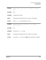
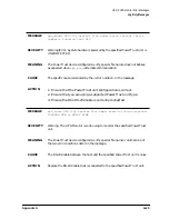
Страница 170: ... error number in the message ACTION Ensure that the correct tty special file name is being used for the RS 232 port to the PowerTrust unit MESSAGE ups_mond UPS tty special file name ioctl TCGETA failed error number ignoring that UPS SEVERITY Warning Error System hardware powered by the specified PowerTrust unit is UNPROTECTED MEANING The PowerTrust device configured as tty special file name could ...

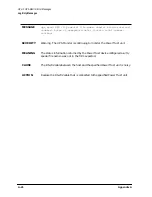
Страница 171: ...ort to the PowerTrust unit MESSAGE ups_mond UPS tty special file name line too noisy ignoring that UPS SEVERITY Warning System hardware powered by the specified PowerTrust unit is UNPROTECTED MEANING The communication link to the PowerTrust device configured as tty special file name has too much noise the UPS Monitor has stopped monitoring the specified PowerTrust unit CAUSE The RS 232 cable to th...

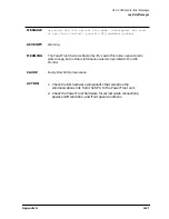
Страница 172: ...the PowerTrust unit configuration is correct 2 Ensure that you are using a supported PowerTrust unit type 3 Ensure that the RS 232 cable is correctly connected MESSAGE ups_mond UPS tty special file name read after enable failed error number ignoring that UPS SEVERITY Warning Error System hardware powered by the specified PowerTrust unit is UNPROTECTED MEANING The PowerTrust device configured as tt...

Страница 173: ...TION 1 Ensure that the PowerTrust unit configuration is correct 2 Ensure that you are using a supported PowerTrust unit type 3 Ensure that the RS 232 cable is correctly connected MESSAGE ups_mond UPS tty special file name read of status received ILLEGAL CMD or NOISY LINE SEVERITY Warning The UPS Monitor is continuing to monitor the specified PowerTrust unit MEANING The PowerTrust device configured...

Страница 174: ...er string SEVERITY Warning The UPS Monitor is continuing to monitor the PowerTrust unit MEANING The status information returned by the PowerTrust device configured as tty special file name was not in the form expected CAUSE The RS 232 cable between the host and the specified PowerTrust unit is noisy ACTION Replace the RS 232 cable that is connected to the specified PowerTrust unit ...

Страница 175: ... specific cause is denoted by the error number in the message ACTION Ensure that the RS 232 cable to the specified PowerTrust unit is correctly connected MESSAGE ups_mond UPS tty special file name write failed error number SEVERITY Warning The UPS Monitor is continuing to monitor the PowerTrust unit MEANING A write by the UPS Monitor to the PowerTrust device configured as tty special file name fai...

Страница 176: ...rust unit has recovered from a previous PowerTrust unit System Fail condition ACTION Continue to monitor the specified PowerTrust unit MESSAGE ups_mond UPS tty special file name turned off Inverter Failure Alarm SEVERITY Information A previous critical or warning condition related to PowerTrust unit Inverter Fail has been corrected MEANING The PowerTrust device configured as tty special file name ...

Страница 177: ...Charger Fault error condition CAUSE The PowerTrust unit has recovered from a previous PowerTrust Charger Fault condition ACTION None MESSAGE ups_mond UPS tty special file name turned off Current Overload Alarm SEVERITY Information A previous critical or warning condition related to a Current Overload has been corrected MEANING The PowerTrust device configured as tty special file name informed the ...

Страница 178: ...s now within acceptable limits CAUSE The PowerTrust unit has recovered from a previous PowerTrust internal High Ambient Temperature condition Room temperature has fallen low enough to remove the overtemperature condition ACTION None MESSAGE ups_mond UPS tty special file name turned off Battery Failure Alarm SEVERITY Information A previous critical or warning condition related to a Battery Failure ...

Страница 179: ...formation A previous critical or warning condition related to High Battery Voltage has been corrected MEANING The PowerTrust device configured as tty special file name informed the UPS Monitor that it has cleared a High Battery Voltage error condition CAUSE The PowerTrust unit has recovered from a previous PowerTrust High Battery Voltage condition ACTION None ...

Страница 180: ... charge threshold The PowerTrust unit has something more than two minutes of battery reserve power available CAUSE The PowerTrust unit has recovered from a previous PowerTrust Low Battery Voltage condition ACTION None MESSAGE ups_mond UPS tty special file name turned off High Output Voltage Alarm SEVERITY Information A previous critical or warning condition related to High Output Voltage has been ...

Страница 181: ...mation A previous critical or warning condition related to Low Output Voltage has been corrected MEANING The PowerTrust device configured as tty special file name informed the UPS Monitor that it has cleared a previous Low Output Voltage error condition CAUSE The PowerTrust unit has recovered from a previous PowerTrust Low Output Voltage condition ACTION None ...

Страница 182: ... to AC power inverter CAUSE The PowerTrust unit detected a failure condition in its power inverter ACTION Call HP Service MESSAGE ups_mond UPS tty special file name Battery Charger Fault requires repair SEVERITY Critical PowerTrust hardware has failed PowerTrust output power is still on but the PowerTrust unit will not be able to protect the system against an AC power failure if one occurs MEANING...

Страница 183: ...Messages section of this appendix CAUSE Improper system hardware installation has put too much load on the PowerTrust unit or a hardware malfunction in the system equipment being powered by the PowerTrust unit has increased the power demand to the point of overload ACTION Call HP Service MESSAGE ups_mond UPS tty special file name High Ambient Temperature reduce area temperature SEVERITY Warning Po...

Страница 184: ...ttery charger circuitry or elsewhere in the PowerTrust unit has caused the battery to fail to perform normally ACTION Call HP Service MESSAGE ups_mond UPS tty special file name High Battery Voltage requires repair SEVERITY Critical PowerTrust hardware has failed PowerTrust power output is still on but the PowerTrust unit will not be able to protect the system against an AC power failure if one occ...

Страница 185: ...e system against an AC power failure if one occurs MEANING The PowerTrust device configured as tty special file name informed the UPS Monitor that the voltage output of its battery is too low The PowerTrust unit can no longer be relied upon to supply battery reserve power in the event of an AC power failure CAUSE A hardware problem in the battery or battery charger circuitry or elsewhere in the Po...

Страница 186: ...t may be faulty it should be replaced MESSAGE ups_mond write to UPS tty special file name Failed error number of command command string SEVERITY Warning Error A command was not sent to the PowerTrust unit MEANING A command to the PowerTrust device configured as tty special file name was not sent due to a write error to that tty CAUSE The specific cause is denoted by the error number in the message...

Страница 187: ...it was successful MEANING After a command was sent to the PowerTrust device configured as tty special file name a read of the status of that command failed CAUSE The specific cause is denoted by the error number in the message ACTION 1 Check the I O hardware components that comprise the communications link from the SPU to the PowerTrust unit 2 Check the PowerTrust hardware for correct cable connec...

Страница 188: ...mprise the communications link from the SPU to the PowerTrust unit 2 Check the PowerTrust hardware for correct cable connections power on off condition and front panel conditions 3 If neither of the first two action steps above corrects the problem the PowerTrust unit is probably faulty and should be replaced MESSAGE ups_mond warning shutdown delay or shutdown timer parameter in configfile configf...

Страница 189: ...t power output is still on but the PowerTrust unit will not be able to protect the system against an AC power failure if one occurs MEANING The PowerTrust device configured as tty special file name is in bypass mode thus cannot provide protection to the system in the event of an AC power failure CAUSE The PowerTrust unit has been set to bypass mode or is faulty ACTION Call HP Service ...

Страница 190: ...A 42 AppendixA HP UX UPS Monitor Error Messages Log Only Messages ...

Страница 191: ...ges your computer system needs MPE iX version 5 0 or later They are organized in the following categories Power Status Messages Alarm Status Messages Alarm Status Cleared Messages Log Only Status Messages NOTE The term UPS Uninterruptible Power System is used in all error messages to refer to the PowerTrust unit The term UPS Monitor refers to the software that monitors PowerTrust operation All mes...

Страница 192: ...UPS Monitor subsystem monitors the conditions of all PowerTrust units on an MPE iX system and notifies the system operator via console messages of any PowerTrust alarm conditions and of system power failures Under some alarm conditions it might not be able to The message may be delayed until AC input power has been restored In other cases the message may be lost ...

Страница 193: ...enough to exhaust the PowerTrust battery no action is needed Otherwise determine what is causing the power loss and restore the power before the PowerTrust battery becomes exhausted MESSAGE UPS LDEV nnn reports AC input power Bypass Mode UPSWRN 0035 CAUSE The specified PowerTrust unit has been placed into its AC Power Bypass Mode of operation This should only occur when the PowerTrust unit is bein...

Страница 194: ... be one or several units in a system detect that normal AC input power is present following a power loss at any PowerTrust unit MESSAGE UPS LDEV nnn reports Low Battery Charge condition UPSWRN 0037 CAUSE The specified PowerTrust unit had lost its AC input power some time ago and has been supplying reserve power from its battery AC input power has not been restored yet causing the battery to be dra...

Страница 195: ... have mistakenly turned off the PowerTrust unit s power switch or the PowerTrust unit may have malfunctioned Whatever equipment was receiving power from the PowerTrust unit has now lost power ACTION Investigate and correct the problem at the PowerTrust unit Turn on all power control switches on the PowerTrust unit If the computer SPU lost power you will have to reboot the system after restoring th...

Страница 196: ...ll HP Service MESSAGE UPS LDEV nnn reports UPS Inverter Fail condition UPSERR 0193 CAUSE The specified PowerTrust unit reported an Inverter Fail condition This is a hardware malfunction condition within the PowerTrust unit The DC to AC power inverter within the PowerTrust unit has malfunctioned ACTION Call HP Service MESSAGE UPS LDEV nnn reports UPS Charger Fault condition UPSERR 0195 CAUSE The sp...

Страница 197: ... installation Correct the system installation to reduce the loading on the PowerTrust unit 3 If the system installation is not the problem find and replace the faulty system hardware component that is overloading the PowerTrust unit MESSAGE UPS LDEV nnn reports UPS High Ambient Temperature Shutdown condition UPSERR 0197 CAUSE The specified PowerTrust unit reported a High Ambient Temperature Shutdo...

Страница 198: ...erTrust unit AC output If the excessive power draw continues the PowerTrust unit may reach an Overload Shutdown condition ACTION 1 Reduce the load on the PowerTrust unit by powering off some non critical system component 2 Check for an improper system hardware installation Correct the system installation to reduce the loading on the PowerTrust unit 3 If the system installation is not the problem f...

Страница 199: ...too warm take steps to cool the room If room temperature is not the problem then replace the faulty PowerTrust unit MESSAGE UPS LDEV nnn reports UPS Battery Test Fail condition UPSERR 0200 CAUSE The specified PowerTrust unit reported a Battery Test Fail condition This is a hardware malfunction within the PowerTrust unit hardware The PowerTrust unit logic perceives that the PowerTrust unit battery ...

Страница 200: ...S Low Battery Voltage condition UPSERR 0202 CAUSE The specified PowerTrust unit reported a Low Battery Voltage condition This is a hardware malfunction within the PowerTrust unit hardware The PowerTrust unit logic perceives that the PowerTrust unit battery is not working properly ACTION Call HP Service ...

Страница 201: ...dware or possibly in the equipment being powered from the PowerTrust unit The PowerTrust unit has shut itself off ACTION Call HP Service MESSAGE UPS Monitor UPS error Lost communications with UPS LDEV nnn That UPS is no longer being monitored UPSERR 0512 CAUSE The UPS Monitor had been monitoring the specified PowerTrust unit LDEV successfully then for some reason lost I O communications with that ...

Страница 202: ...nable to start monitoring on UPS Ldev nnn due to File System error in finding or opening the device UPSWRN 0587 CAUSE This is a software detected error condition that indicates an error in the UPS Monitor software or in some other system software or a system memory error ACTION Call the Response Center ...

Страница 203: ...orted problem has been corrected MESSAGE UPS LDEV nnn reports UPS Inverter Fail condition cleared UPSWRN 0129 CAUSE Some time ago the specified PowerTrust unit had reported a Inverter Failure condition Now the Inverter Failure condition within the PowerTrust unit has been corrected and the PowerTrust unit is reporting a return to normal operation ACTION No action is needed This message merely conf...

Страница 204: ...on cleared UPSWRN 0133 CAUSE Some time ago the specified PowerTrust unit had reported a UPS High Ambient Temperature Shutdown condition Now the High Ambient Temperature Shutdown condition has been corrected and the PowerTrust unit is reporting a return to normal operation ACTION No action is needed This message merely confirms that a previously reported problem has been corrected MESSAGE UPS LDEV ...

Страница 205: ...SWRN 0135 CAUSE Some time ago the specified PowerTrust unit had reported a High Ambient Temperature condition Now the High Ambient Temperature condition has been corrected and the PowerTrust unit is reporting that it has returned to normal operation ACTION No action is needed This message merely confirms that a previously reported problem has been corrected ...

Страница 206: ...0137 CAUSE Some time ago the specified PowerTrust unit had reported a High Battery Voltage condition Now the High Battery Voltage condition in the PowerTrust unit has been corrected and the PowerTrust unit is reporting a return to normal operation ACTION No action is needed This message merely confirms that a previously reported problem has been corrected MESSAGE UPS LDEV nnn reports UPS Low Batte...

Страница 207: ...ng a return to normal operation ACTION No action is needed This message merely confirms that a previously reported problem has been corrected MESSAGE UPS LDEV nnn reports UPS Low Output Voltage Shutdown condition cleared UPSWRN 0140 CAUSE Some time ago the specified PowerTrust unit had reported a Low Output Voltage Shutdown condition Now the Low Output Voltage Shutdown condition has been corrected...

Страница 208: ...O cable or a PowerTrust unit hardware malfunction ACTION 1 Check for proper connection of the PowerTrust unit I O interface cable at both ends 2 Ensure that the PowerTrust unit is powered on NOTE Even after correcting cable or connection problems the system must be rebooted before the software will attempt to resume monitoring the UPS MESSAGE UPS LDEV nnn I O Operation error The actual Read data t...

Страница 209: ...at the PowerTrust unit is powered on 3 Check that the system I O configuration is correct NOTE Even after correcting cable or connection problems the system must be rebooted before the software will attempt to resume monitoring the UPS MESSAGE UPS Monitor warning Too many UPS devices have been configured in the system I O configuration files The UPS Monitor cannot monitor all of them it will monit...

Страница 210: ...t units have been configured in the system s I O configuration files This is an error if this system is supposed to have PowerTrust units on it This is not an error if this system is not supposed to have PowerTrust units on it ACTION If this system is supposed to have PowerTrust units on it review and correct the system I O configuration then restart the system If this system is not supposed to ha...

Страница 211: ...X or MPE iX system for the PowerTrust UPS For specific instructions about configuring the PowerTrust UPS into your system refer to the System Administration Task Manual for HP UX servers or to Configuring Systems for Terminals Printers and Other Serial Devices for MPE iX systems Instructions for how to power fail a system are in the last section of this appendix ...

Страница 212: ...her or MPE iX 4 7 or higher 3 The operating system configuration is modified to recognize the UPS If the PowerTrust UPS is not added to the computer s configuration table the UPS will still perform power conditioning and supply battery backup but there are two limitations 1 The error message information in Appendix A HP UX UPS Monitor Error Messages and Appendix B MPE iX UPS Monitor Error Messages...

Страница 213: ...ud rate b Activate or deactivate the automatic shutdown feature c The shutdown_delay_mins parameter default 1 minute This parameter specifies the number of minutes the UPS Monitor program will wait before initiating a shutdown h following notification that AC power to the UPS is lost This interval allows the computer to continue operation through brief electrical fluctuations To take full advantag...

Страница 214: ...andard 9 pin RS 232 connector it has a non standard pin out You must use one of these RS 232 cables 5061 2575 DB9 9 pin male DB9 9 pin female 2 5 meter 5061 2569 DB9 9 pin male DB25 25 pin male 2 5 meter 5063 5352 DB9 9 pin male DB25 25 pin male 4 meter c Check that the port is configured at 1200 baud rate d Verify that the configured port value corresponds to the physical port used for the UPS co...

Страница 215: ...rmation on using SYSGEN to view and modify the configuration see Chapter 2 of the CS 99x T Class Installation Guide 3 Use NMMGR to configure the DTC port for each UPS A port connected to a UPS is configured similar to a terminal Use a profile with the following parameters a Set the field Allow HELLO logon to N b Set the first device class name field to HPUPSDEV c Set the baud rate to 1200 d Set al...

Страница 216: ...25 25 pin male 2 5 meter c Verify that the value entered in NMMGR for the port corresponds to the physical port used on the DTC d Verify these UPS terminal profile parameters Baud rate 1200 No parity Terminal type 10 First and only device class name HPUPSDEV e Power cycle the DTC to force the DCC Data Comm Configurator to download the DTC as the system finishes booting This is needed to get the ba...

Страница 217: ...ress 080009281E05 Wait 30 seconds after that message appears and then perform the power fail test For either HP UX or MPE iX systems use this procedure to power fail a system 1 Check that the system is not performing critical processes 2 Use the wall breaker to cut the power for the circuit that is supplying power to the UPS Do NOT use the rear panel circuit breaker to power fail the system 3 Wait...

Страница 218: ...C 8 AppendixC Configuring the OS for the PowerTrust UPS Power Failing the UPS ...

Страница 219: ...Appendix D D 1 Field Replaceable Units D Field Replaceable Units This appendix documents The Field Replaceable Units FRUs for the UPS Removal and replacement procedures for all FRUs ...

Страница 220: ...it 40A North American power 0950 3292 Service Bypass Unit 40A European power 0957 0269 5 5 kVA UPS Electronics Unit exchange 0957 0270 Service Bypass Unit 30A hardwired power exchange 0957 0271 Service Bypass Unit 30A North American power exchange 0957 0268 Conversion Kit Worldwide to North American 30A 0957 0274 Conversion Kit North American to Worldwide 30A includes two strain reliefs 0957 0285 ...

Страница 221: ... PDU Output Convenience Cable male C14 to female C13 8ft 8120 6366 PDU Output Convenience Cable male C14 to female C13 5m 5061 2569 Pinout DB 9 DB 25 Male Male UPS Host 1 RX 3 TX 2 TX 2 RX 9 GND 7 GND 5061 2575 Pinout DB 9 DB 9 Male Femal e UPS Host 1 RX 3 TX 2 TX 2 RX 9 GND 5 GND 5063 5352 Pinout DB 25 DB 9 Male Male UPS Host 1 RX 2 TX 2 TX 3 RX 9 GND 7 GND HP Part No Description ...

Страница 222: ...personnel only Removing and Replacing UPS Electronics Unit Tools required 25 Torx driver Flathead screwdriver To replace the Electronics Unit 1 Make sure the BYPASS and MAIN INPUT breakers are ON CAUTION If the yellow caution light is flashing do not proceed Switching the UPS into Bypass mode when the caution light is flashing may disrupt power to the load Call HP Service If the yellow caution lig...

Страница 223: ...rewdriver to loosen the screw at the center of each captive thumbscrew 14 Connect the battery cable to the connector on the Electronics Unit 15 Check the Battery Precharge Failure LED see 15 in Figure 1 3 If the LED is off continue If the LED is on do not reinstall the Battery Precharge Shorting Plate Refer to Case 14 Abnormal Battery Precharge Failure in Chapter 6 16 Orient the plate so that the ...

Страница 224: ...ON Do not leave the Output On Output Off switch in the Output Off position for more than 5 seconds Doing so will turn off AC output to the receptacles and power down the load 23 Position the front bezel onto the brackets so that the pins behind the front of the bezel line up with the four brackets on the face of the Electronics Unit See Figure D 6 24 Push the bezel in until the bezel pins snap int...

Страница 225: ...eplacing the battery packs on one side replace the battery packs on the other side one at a time 1 Make sure the BYPASS and MAIN INPUT breakers are ON CAUTION If the yellow caution light is flashing do not proceed Switching the UPS into Bypass mode when the caution light is flashing may disrupt power to the load Call HP Service If the yellow caution light is not flashing continue 2 While depressin...

Страница 226: ...e Figure 3 3 You may need to rock the battery slightly if the battery binds on the tracks 11 Fasten the thumbscrew at the bottom of the battery pack 12 Put the old battery pack in the shipping container from which you took the new battery pack and follow the return and disposal procedures that were shipped with the replacement battery pack 13 Repeat steps 7 through 12 for the remaining battery pac...

Страница 227: ...than 5 seconds Doing so will turn off AC output to the receptacles and power down the load 23 Replace the filler panels NOTE After replacing the battery packs check that the computer is not performing critical processes then repeat the load test For procedures refer to Load Testing in Chapter 5 Also after installing replacement UPS equipment test it by power failing the UPS For procedures refer to...

Страница 228: ...tery pack 13 Reattach the Battery Box cable to the Electronics Unit After you attach the cable the capacitors will precharge 14 Check the Battery Precharge Failure LED see 15 in Figure 1 3 If the LED is off continue If the LED is on do not reinstall the Battery Precharge Shorting Plate Refer to Case 14 Abnormal Battery Precharge Failure in Chapter 6 15 Orient the plate so that the notch on the pla...

Страница 229: ...ence Alarm Test switch on the control panel 24 Switch the Output On Output Off switch to Output On The Caution LED should flash for about five seconds then go out 25 When the Caution LED stops flashing go to step 26 If it continues to blink refer to Caution LED in Chapter 6 for possible causes and actions 26 Turn the Bypass switch to Normal 27 To clear the alarm if you have not already done so and...

Страница 230: ...l when the last screw is removed 6 Carefully but firmly pull on the Service Bypass Unit to disconnect it from the Electronics Unit and remove it from the rack 7 Check that the Service Bypass switch on the new UPS is set to NORMAL and that the breakers are all off 8 Slide the Service Bypass Unit onto the shelf of the Electronics Unit until the connector at the back of the Electronics Unit is aligne...

Страница 231: ...ce Bypass Unit only and should be performed by a qualified electrician The Hardwire Conversion Kit contains the following items 1 Metal plate preassembled with 2 plastic strain reliefs 4 Torx screws 25 10 32 x 1 2 2 Labels Tools required 25 Torx driver Flathead screwdriver Wire cutter wire stripper Removing the existing conversion plate if any 1 If the UPS is operating shut it down using the follo...

Страница 232: ...n the rear panel 2 Reinstall the left Access Panel on the rear panel using the four Torx screws that were removed earlier 3 Apply the Hardwire Conversion Kit labels to the shipping container and pack the unit Contact the local Hewlett Packard Sales and Service Office for repacking information and materials B If the wiring is done on site 1 Wire gauge requirements for new hardwired installations a ...

Страница 233: ...n the right d Position each cord so that the outer covering of the cords protrudes 2 54 cm 1 0 in past the inside end of the strain relief bodies Hand tighten both bushings to secure the cords Installing conduit connectors The plate has 1 23 64 holes that can accommodate conduit connectors in place of strain reliefs Remove the strain reliefs and replace them with suitable conduit connectors Attach...

Страница 234: ...ct wire to the L1 terminal Neutral or Line 2 Connect wire to the L2 N terminal Earth Ground Connect the GREEN or GREEN YELLOW wire to the terminal marked with the following symbol Tighten the terminal block screws to the following torque specifications For Line and Ground Terminals 1 2 1 4 Nm 10 6 12 3 lb in 5 If all repairs to the UPS have been completed or if the UPS is being converted on site i...

Страница 235: ...ns the following items 1 Metal plate preassembled with a 3 pin L6 30 twist lock receptacle and a line cord 4 Torx screws 25 10 32 x 1 2 2 Labels Tools required 25 Torx driver Flat blade screwdriver Removing the existing conversion plate if any 1 If the UPS is operating shut it down using the following procedure a Turn the Output On Output Off switch to Output Off b Turn the UPS BATTERY switch to D...

Страница 236: ... four Torx screws supplied with the kit Make certain that the conversion plate is positioned over the right opening in the rear panel 2 Connect the wires as follows Input Wiring line cord Connect the BLACK 30A or BROWN 40A wire to the L1 terminal Connect the WHITE 30A or BLUE 40A wire to the L2 N terminal Connect the GREEN or GREEN YELLOW wire to the input ground terminal marked with the following...

Страница 237: ...RY switch to ENABLE Wait for the green Enable LED to come on d Check that the Caution LED is off If it is on refer to Caution LED in Chapter 6 e Turn the Output On Output Off switch to Output On 5 If the UPS is being converted for use elsewhere apply the North American Conversion Kit labels to the shipping container and pack the unit Contact the local Hewlett Packard Sales and Service Office for r...

Страница 238: ...e and a circuit board inside See Figure D 5 4 Torx screws 25 10 32 x 1 2 Tools required 25 Torx driver 1 4 inch hex nut driver for control panels with underside cable connector only Phillips head screwdriver Figure D 4 Control Panel Assembly To remove and replace the Control Panel and Label Kit 1 Make sure the BYPASS and MAIN INPUT breakers are ON ...

Страница 239: ...ics Unit 6 Remove the bezel assembly and the four Torx screws that secure the Electronics Unit to the rack 7 Remove the old panel assembly by removing the four Torx screws that hold it to the front of the Electronics Unit 8 Disconnect the cable from the circuit board by grasping the red connector and gently pulling it out from the 10 pin right angle header on the side of the circuit board 9 Instal...

Страница 240: ...he plate making sure that the prongs on the plate are pressed firmly into the clips in the Electronics Unit See Figure 3 9 CAUTION Operating the UPS without the Battery Precharge Shorting Plate is not supported and may result in loss of UPS AC output 13 Tighten the thumbscrews on either side of the Battery Precharge Shorting Plate 14 Switch the UPS BATTERY switch to ENABLE Wait for the green Enabl...

Страница 241: ... seconds Doing so will turn off AC output to the receptacles and power down the load 19 Position the front bezel onto the brackets so that the pins behind the front of the bezel line up with the four brackets on the face of the Electronics Unit See Figure D 7 20 Push the bezel in until the bezel pins snap into the bracket clips NOTE After replacing the Control Panel and Label Kit check that the co...

Страница 242: ...ollowing procedure should be performed by qualified service personnel only The fan assembly kit contains the following items 1 Fan assembly See Undefined Cross Reference 6 Torx screws 25 10 32 x 1 2 Tools required 25 Torx driver Flathead screwdriver Figure D 7 Fan Assembly NOTE The fan assembly must be replaced as a module Do not disassemble it ...

Страница 243: ...Unit 6 Remove the bezel assembly 7 Set the MAIN INPUT breaker to OFF 8 Set the UPS BATTERY switch to ENABLE The green enable LED will turn on until the capacitors are discharged 9 When the green LED turns off set the switch to DISABLE 10 Remove the fan a Remove the four Torx screws that hold the fan assembly to the front of the UPS b Carefully remove the fan assembly from the UPS front panel While...

Страница 244: ...If it is blinking refer to Caution LED in Chapter 6 for possible causes and actions 19 Turn the Bypass switch to Normal 20 To clear the alarm if you have not already done so and return to normal operation from Bypass mode turn the control panel Output On Output Off switch to Output Off for about one second then return it to the Output On position CAUTION Do not leave the Output On Output Off switc...

Страница 245: ...Procedures This appendix gives an overview of the 40A Service Bypass Unit In general the specification and procedures described in the body of this manual are the same for both the 30A and 40A Service Bypass Units However there are minor differences between them and those differences are explained in this appendix ...

Страница 246: ...e 30A and the 40A Service Bypass Units are shown in Figure E 1 Figure E 1 40A Service Bypass Unit 1 AC Power Input A line cord with an IEC 309 363P6 plug attached Used to connect the North American version of the UPS to an AC source or wall outlet 2 AC Output One line cord with IEC 309 363C6 receptacle attached An SPU is connected to this receptacle ...

Страница 247: ...otect the UPS from overcurrent conditions The first three output circuit breakers marked OUTLET 1 OUTLET 2 and OUTLET 3 provide overcurrent protection for the IEC320 C19 outlets see 2 in Figure 1 3 The circuit breaker marked OUTLET 4 provides overcurrent protection for the IEC 309 363C6 output cord mounted receptacle see 2 Figure E 1 in 5 IEC Output Receptacles Three IEC320 C19 output receptacles ...

Страница 248: ...ning the Service Bypass Unit top box 2 Open the carton 3 Remove materials such as manuals from the top of the box and set them aside 4 Lift both cords then remove the packaging that supports the cords by letting the cords pass through the opening in the cardboard See Figure E 2 Figure E 2 Unpacking the 40A PowerTrust Service Bypass Unit 5 Remove the L shaped corrugated cardboard pads from the top ...

Страница 249: ...nd Procedures Unpacking the Service Bypass Unit 6 Check the packing material for signs of damage which could indicate rough handling during transit Refer to Claims Procedures in Chapter 2 if you discover any damage 7 Carefully remove the Service Bypass Unit ...

Страница 250: ...nect the SPU 1 Position the expansion cabinet containing the PowerTrust UPS close to the AC input source 2 Make sure that the power switches of the SPU and test station are OFF 3 Connect the UPS input power cord IEC 309 363P6 plug 1 in Figure E 1 to the AC power source 4 Plug the SPU power cord into the IEC 309 363C6 cord mounted receptacle 5 Connect the Mux port module power cord to the PDU in th...

Страница 251: ...Appendix E E 7 40A Service Bypass Unit Specifications and Procedures Connecting the SPU to the UPS 40A Service Bypass Unit Only Figure E 3 Power and Communication Line Connections ...

Страница 252: ...screw driver 3 Attach the other end of the RS 232 cable to a RS 232 connector on the Mux port module Refer to Figure E 3 Connecting the Test Station It is recommended that the test station for the V Class SPU be connected to another UPS It is further recommended that the communications cable for the test station UPS not be connected to the Mux port module but rather directly to the test station Fi...

Страница 253: ... chemicals 1 37 circuit breakers 1 13 1 18 claims procedures shipping 2 11 cleaning the PowerTrust 7 1 communications cable connecting E 8 communications link connecting 3 17 communications port 1 12 1 17 configuration examples 3 19 E 8 frequency 1 31 voltage 1 31 configuring the PowerTrust for HP UX C 1 for MPE iX C 5 for MPE iX with NMMGR C 5 connecting communications cable E 8 communications li...

Страница 254: ...34 ups_mond UPS tty special file name Battery Failure requires repair A 36 ups_mond UPS tty special file name battery low A 14 ups_mond UPS tty special file name could not enable ignoring that UPS A 24 ups_mond UPS tty special file name could not execute command command string returned string possible bad signal cable A 40 ups_mond UPS tty special file name current overload A 16 ups_mond UPS tty s...

Страница 255: ...ed error number of command command string A 38 usage ups_mond f configfile s A 8 I IEC output receptacles 1 12 1 16 E 2 ignored A 5 indicators 6 6 input and output connections 3 14 input wiring North American version 3 14 worldwide version 3 16 D 15 inventorying the PowerTrust shipment 2 2 L lights AC Output 6 6 Attention 6 6 Battery Power 6 6 Caution 1 15 1 20 6 6 enable 1 15 1 20 indicators 6 6 ...

Страница 256: ...oad condition cleared UPSWRN 0134 B 14 UPS LDEV nnn reports UPS System Fail condition cleared UPSWRN 0128 B 13 UPS LDEV nnn reports UPS System Fail condition UPSERR 0192 B 6 UPS Monitor UPS error Lost communications with UPS LDEV nnn That UPS is no longer being monitored UPSERR 0512 B 11 UPS Monitor warning Too many UPS devices have been configured in the system I O configuration files The UPS Mon...

Страница 257: ...y pack 7 4 Service Bypass mode 1 8 1 14 service bypass mode 1 19 1 33 4 5 service bypass switch 1 14 1 19 Service Bypass Unit unpacking E 4 service bypass unit 1 21 40A E 1 installing 3 8 removing and replacing D 11 unpacking 2 4 shipping claims procedures 2 11 shipping pallet 2 4 breaking 2 4 shipping requirements 2 12 shutdown_delay_mins parameter C 3 shutdown_timeout_mins parameter C 3 shutdown...

Отзывы: