


Chapter 4
4-5
Power-On/Power-Off Procedures
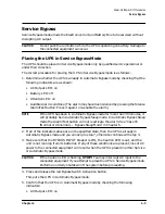
Service Bypass
Service Bypass
Service Bypass mode allows the Electronics Unit and Battery Box to be serviced without
disrupting AC output.
CAUTION
Do not push the red button while the UPS is operating on battery. Damage to
the connected equipment can occur.
Placing the UPS in Service Bypass Mode
The UPS should be placed in Service Bypass mode only by qualified service personnel or
under their direction.
The correct procedure for placing the UPS in Service Bypass mode is as follows:
1. Determine whether the UPS is already in Automatic Bypass mode by checking that the
following indicators are as shown:
• AC Output LED: on
• Battery LED: off
• Attention LED: on
• Audible Alarm: solid tone (The alarm may have been silenced by pressing the Silence
Alarm/Test button. Press it again to re-enable the alarm.)
NOTE
If the UPS has been in Automatic Bypass mode for more than 30 minutes, it
will probably be in Automatic Bypass Sleep mode. In Automatic Bypass Sleep
mode the Alarm/Test button will not reactivate the alarm. See “Case 16
(Normal or Abnormal) — Bypass Sleep Mode” in Chapter 6.
2. If all of the indicators above are in the specified state, then the UPS is already in
Automatic Bypass mode and you can skip to step 7, otherwise continue with step 3.
3. Make sure that the BYPASS INPUT breaker is ON, the Caution LED is out, and the
unit is not running from its batteries. If any of these conditions are present, loss of AC
power to the connected equipment will result when the UPS is placed in either Service
or Automatic Bypass mode.
CAUTION
If the Caution LED is flashing, STOP! You may interrupt AC input to the
connected equipment if you attempt to place the UPS in Service Bypass mode.
Perform an orderly shutdown of the system before proceeding.
4. Press and release the red Bypass Switch Activation button.
This puts the UPS in Automatic Bypass mode.
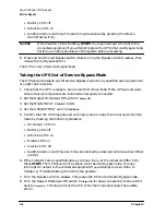
5. Confirm that the UPS is in Automatic Bypass mode by checking the following
indicators:
• AC Output LED: on
Содержание PowerTrust A3589A
Страница 7: ...Contents Contents 5 ...
Страница 8: ...Contents 6 Contents ...
Страница 10: ...Contents 8 Figures ...
Страница 12: ...Contents 10 Tables ...
Страница 14: ...2 ...
Страница 20: ...Preface 8 ...
Страница 22: ...Preface 10 ...
Страница 52: ...1 30 Chapter1 Overview Specifications Figure 1 8 UPS Input Voltage Transfer Points ...
Страница 56: ...1 34 Chapter1 Overview UPS Modes Figure 1 10 Simplified UPS 5 5 kVA UPS Block Diagram ...
Страница 62: ...1 40 Chapter1 Overview Support Information ...
Страница 76: ...2 14 Chapter2 Unpacking and Inspecting Shipping and Storage Requirements ...
Страница 104: ...3 28 Chapter3 Installing the UPS Examples of PowerTrust Connections in a System ...
Страница 116: ...5 4 Chapter5 Verification Procedures Load Testing ...
Страница 148: ...7 6 Chapter7 Cleaning and Maintenance Exchanging Batteries Fan ...
Страница 190: ...A 42 AppendixA HP UX UPS Monitor Error Messages Log Only Messages ...
Страница 218: ...C 8 AppendixC Configuring the OS for the PowerTrust UPS Power Failing the UPS ...