background image

EIO00000015

05.01

www.schneider-electric.com

Harmony eXLhoist

EIO0000001505 04/2014

Harmony eXLhoist

Wireless Remote Control System

User Guide

12/2014

Содержание eXLhoist

Страница 1: ...EIO0000001505 01 www schneider electric com Harmony eXLhoist EIO0000001505 04 2014 Harmony eXLhoist Wireless Remote Control System User Guide 12 2014...

Страница 2: ...any suggestions for improvements or amendments or have found errors in this publication please notify us No part of this document may be reproduced in any form or by any means electronic or mechanical...

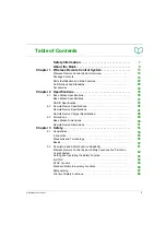
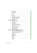
Страница 3: ...cification 43 2 2 Remote Device Specifications 46 Remote Device Specifications 47 Remote Device Charger Specification 48 2 3 Dimensions 49 Base Station Dimensions 50 Remote Device Dimensions 51 Chapte...

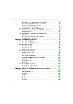
Страница 4: ...pter 4 Installation and Wiring 81 4 1 Base Station Installation 82 Base Station Installation Precaution 82 4 2 Base Station Wiring 86 Base Station Wiring 87 Wiring Best Practices 91 Factory Setting De...

Страница 5: ...RT D Diagnostic 149 Diagnostic Mode 150 Radio Communication Indicator 152 Battery Level of the Remote Device 153 E STOP LED 154 Applicative Alarms Signals 155 Detected Failure Displays 156 6 3 ZART8L...

Страница 6: ...Identity 189 Parameters 191 Relay Assignment 194 Interlocking 198 Detected Applicative Alarms 199 Chapter 8 Maintenance Device Replacement 201 8 1 Maintenance 202 Regular Cleaning 202 8 2 Device Repla...

Страница 7: ...and look at the equipment to become familiar with the device before trying to install operate or maintain it The following special messages may appear throughout this documentation or on the equipment...

Страница 8: ...nel No responsibility is assumed by Schneider Electric for any consequences arising out of the use of this material A qualified person is one who has skills and knowledge related to the construction a...

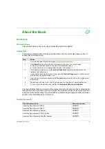
Страница 9: ...ct or the name of a product range Do not include blank spaces in the model number product range To get information on grouping similar modules use asterisks 3 If you entered a reference go to the Prod...

Страница 10: ...n this user guide Always use a properly rated voltage sensing device to confirm that the power is off Unplug the power cable from both the equipment and the power supply Replace and secure all covers...

Страница 11: ...be collected separately and returned to an environmentally compatible recycling facility in accordance with national law In case of electrolyte leak from battery use adapted safety equipment and put...

Страница 12: ...12 EIO0000001505 12 2014...

Страница 13: ...eless Remote Control System Chapter 1 Wireless Remote Control System What Is in This Chapter This chapter contains the following topics Topic Page Wireless Remote Control System Overview 14 Package Co...

Страница 14: ...r transmitter which is the operator command device to interface with the machine Base Station or receiver which is hardwired to the machine It receives control commands from the Remote Device and tran...

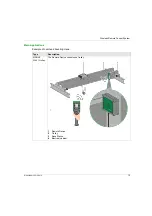
Страница 15: ...ystem EIO0000001505 12 2014 15 Main Applications Example of overhead traveling crane Type Description SINGLE With 1 trolley The Remote Device controls one trolley 1 Remote Device 2 Trolley 3 Base Stat...

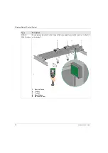
Страница 16: ...001505 12 2014 SINGLE With 2 trolleys By using the selector button the Remote Device separately controls the trolley 1 trolley 1 2 or the trolley 2 1 Remote Device 2 Trolley 1 3 Trolley 2 4 Base Stati...

Страница 17: ...tem EIO0000001505 12 2014 17 SINGLE With 2 hooks By using the selector button the Remote Device separately controls the hook 1 or the hook 2 1 Remote Device 2 Hook 1 3 Hook 2 4 Base Station 5 Electric...

Страница 18: ...M mode will be available on Q4 2014 TANDEM By using the selector button the Remote Device separately controls the bridge 1 bridge 1 2 or the bridge 2 1 Remote Device 2 Base Station 1 3 Bridge 1 4 Base...

Страница 19: ...erview Applicable items included in the package 1 Base Station 2 Remote Device 3 Set of labels to customize the Remote Device buttons 4 Instruction Sheet 5 Charger of the Remote Device battery only in...

Страница 20: ...relays 12 18 Features ZART8L ZART8D ZART12D Number of configurable buttons 8 8 12 Operator interface LEDs Display Display Complexity level description Reference Wireless Remote Control System Remote...

Страница 21: ...05 12 2014 21 Base Station Parts Identification XARS8KD18H XARS8D18H ZARC01 ZARC02 XARSK12D18W XARS12D18W ZARC01 ZARC02 XARSK12D18H XARS12D18H ZARC01 ZARC02 Reference Starting Kit System Accessories S...

Страница 22: ...enna covered by cap B Status LEDs C M20 for the safeguarding function input wires covered by cap D 62 pins connector covered by cap E M25 for output wires covered by cable gland F M25 for detected app...

Страница 23: ...Inputs dedicated for safeguarding function 0 12 IN7 IN18 Motion auxiliary standard relays 12 Q1 Q12 18 Q1 Q18 Power supply 24 240 V ac dc 24 48 V ac dc 24 240 V ac dc 24 48 V ac dc Current consumptio...

Страница 24: ...Wireless Remote Control System 24 EIO0000001505 12 2014 Remote Device Front View Parts Identification ZART8L ZART8D ZART12D...

Страница 25: ...12 2014 25 Remote Device Rear View Parts Identification 1 Cover 2 RJ45 connector 3 Reset button Part Description 1 1H 2 2H 3 3H 4 4H 5 6 Motion buttons 7 Trigger button 8 OFF STOP button 9 ON START Ho...

Страница 26: ...ice Bottom Display Parts Identification 1 Remote Device battery charge connector 2 Protective plug 3 E STOP button DANGER OBSTRUCTED PUSH BUTTON MOTION Ensure push button will fully operate Failure to...

Страница 27: ...Control System EIO0000001505 12 2014 27 ZART D Display Parts Identification 1 Battery level 2 Radio communication level 3 Operating status 4 Bridge label 5 Detected applicative alarms 6 Selector stat...

Страница 28: ...STOP button Yes ON START Horn button Yes Motion Stop function Yes Selector 2 or 3 positions 1 1 2 2 Yes E STOP function Yes Optional E STOP reset code sequence Yes Optional START code sequence Yes Op...

Страница 29: ...13849 2 EN IEC 62061 EN IEC 61508 EN ISO 13850 Specific standards for hoisting applications EN IEC 60204 32 EN 13557 Low voltage equipment EN IEC 61010 1 EN IEC 60947 5 1 EN IEC 60947 5 4 EN IEC 60947...

Страница 30: ...andards for safety UL 1998 Covered by IEC 61508 UL 991 Canadian specific standards for safety CSA 22 2 N 0 8 Covered by UL 991 Standards for radio frequencies ETSI EN 301 489 1 ETSI EN 301 489 3 ETSI...

Страница 31: ...ce SIRIM Malaysia See on the device COFETEL Mexico See on the device ictQATAR Qatar EAC Russia See on the device IDA Singapore ICASA South Africa See on the device KCC South Korea See on the device NC...

Страница 32: ...Wireless Remote Control System 32 EIO0000001505 12 2014 TRA United Arab Emirates FCC USA See on the device Certification organism Certification organism country Certification marks...

Страница 33: ...nt bloc Use this accessory in case of applications with severe vibration constraints NSYAEFTB Optional mounting Use this accessory for external mounting on support x4 To be assembled on box before mou...

Страница 34: ...Wireless Remote Control System 34 EIO0000001505 12 2014...

Страница 35: ...t EIO0000001505 04 2014 Specifications Chapter 2 Specifications What Is in This Chapter This chapter contains the following sections Section Topic Page 2 1 Base Station Specifications 36 2 2 Remote De...

Страница 36: ...1505 12 2014 Base Station Specifications Section 2 1 Base Station Specifications What Is in This Section This section contains the following topics Topic Page Base Station Specifications 37 RADIO Spec...

Страница 37: ...21 3 3 Level 3C2 on H2S SO2 NO2 Cl2 Fire withstands Power on parts 960 C 30s 30s according to IEC 60695 2 10 and IEC 60695 2 11 Other parts 650 C 30s 30s according to IEC 60695 2 10 and IEC 60695 2 11...

Страница 38: ...ications Details Value ZARB H ZARB W Specifications Details Value Safety relays function Safety specifications According to IEC 61508 Ed2 Up to SIL3 capability According to IEC 62061 Ed1 Up to SIL3 CL...

Страница 39: ...aximum Ie current 24 240 Vac 4 A 6 A Relay type according to EN IEC 60947 5 1 AC15 C300 B300 DC13 R300 Maximum making and breaking capacities 100 000 cycles AC15 AC current according to EN IEC 60947 5...

Страница 40: ...24 240 V ac dc 20 Relay type according to EN IEC 60947 5 1 AC15 B300 DC13 R300 Maximum making and breaking capacities 1 000 000 cycles for NO contacts 500 000 cycles for NC contacts AC15 AC current ac...

Страница 41: ...g 3644 lb 1430 kg 3831 lb 1450 kg 3885 lb Specifications Details Value ZARB12H ZARB12W ZARB18H ZARB18W NOTICE INOPERABLE EQUIPMENT The ZARB H Base Station must be powered with a voltage From 24 Vac 15...

Страница 42: ...ent IN1 IN18 The IN1 to IN18 input specifications are Static input type Current source logic Compatible only with 2 wiring Connection of INi i 1 18 in one side of a dry contact and connection of IN_CO...

Страница 43: ...ion est autoris e aux deux conditions suivantes 1 l appareil ne doit pas produire de brouillage et 2 l utilisateur de l appareil doit accepter tout brouillage radio lectrique subi m me si le brouillag...

Страница 44: ...rth for an uncontrolled environment under the following conditions 1 This equipment should be installed and operated such that a minimum separation distance of 20 cm is maintained between the radiator...

Страница 45: ...munication satisfaisante Les pr sents metteurs radio identifier IC 7002CZARBo and IC 7002CZARTo ont t approuv par Industrie Canada pour fonctionner avec le type d antenne ZARC03 ayant un gain admissib...

Страница 46: ...14 Remote Device Specifications Section 2 2 Remote Device Specifications What Is in This Section This section contains the following topics Topic Page Remote Device Specifications 47 Remote Device Cha...

Страница 47: ...3 Level of 3C2 on H2S SO2 NO2 Cl2 Degree of protection IP65 and NEMA type 4 Altitude Operation Storage 0 2000 m 0 6561 7 ft 0 3000 m 0 9842 5 ft Vibration resistance Conforming to IEC 60068 2 6 10 55...

Страница 48: ...ight industrial environment IEC 61000 6 3 Product certifications CE UL CSA CCC Gost Degree of protection IP2x Degree of pollution 2 Operating temperature 10 40 C 50 104 F Storage temperature for 1 yea...

Страница 49: ...EIO0000001505 12 2014 49 Dimensions Section 2 3 Dimensions What Is in This Section This section contains the following topics Topic Page Base Station Dimensions 50 Remote Device Dimensions 51...

Страница 50: ...50 EIO0000001505 12 2014 Base Station Dimensions Dimensions The following figure shows the Base Station dimensions...

Страница 51: ...EIO0000001505 12 2014 51 Remote Device Dimensions Dimensions The following figure shows the Remote Device dimensions...

Страница 52: ...52 EIO0000001505 12 2014...

Страница 53: ...Chapter 3 Safety What Is in This Chapter This chapter contains the following sections Section Topic Page 3 1 Generalities 54 3 2 Description and Safety Function Capability 61 3 3 Functional Safety Fu...

Страница 54: ...afety 54 EIO0000001505 12 2014 Generalities Section 3 1 Generalities What Is in This Section This section contains the following topics Topic Page Introduction 55 Standards and Terminology 56 Basics 5...

Страница 55: ...ome safety functions are configured with eXLhoist Configuration Software Integrated safety functions provide the following benefits Additional standards compliant safety functions No need for external...

Страница 56: ...of Conformity The EC declaration of conformity for the machine directive 2006 42 EC can be obtained on www schneider electric com Functional Safety Certification The integrated safety functions are co...

Страница 57: ...s considered as a unit This function chain must meet the requirements of the specific safety integrity level as a whole Systems and components that can be used in various applications for safety tasks...

Страница 58: ...road categories hardware safety integrity and systematic safety integrity A device or system must meet the requirements for both categories to achieve a given SIL The SIL requirements for hardware saf...

Страница 59: ...is specified as a safety requirement in the form of a target probability of a dangerous failure over a given period stated as a discrete SIL level PL Performance Level The standard IEC 13849 1 defines...

Страница 60: ...are specified on the basis of criteria which the standard defines for the safety relevant components Systematic Safety Integrity Detect Fault Avoidance Measures Systematic errors in the specifications...

Страница 61: ...Wireless Remote Control System Safety Functions Are Part of an Overall System 62 Getting and Operating the Safety Function 63 E STOP 64 STOP Function 65 Standard Motion Auxiliary Functions 66 Safeguar...

Страница 62: ...rview The qualitative and quantitative safety objectives determined by the final application require some adjustments to ensure safe use of the safety functions The integrator of the Wireless Remote C...

Страница 63: ...safety standard or level of their machine in the context of ISO 13849 1 The tool allows you to model the structure of safety related control components based on the designated architectures allowing...

Страница 64: ...contactors or drives must be by different path The standard E STOP function of eXLhoist is limited to a stop category 0 according to IEC 60204 32 If some applications require an E STOP function with a...

Страница 65: ...masking of STOP activation The safe state of the STOP function is to open safety relays STOP function is a passive stop function activated when an invalid frame is detected Function Installation IEC 6...

Страница 66: ...the unintended standard motion or auxiliary function activation The safe state of the standard motion auxiliary function is to open safety relays In order to justify of the safety category 2 an automa...

Страница 67: ...of the safety category 2 an automatic diagnostic is realized on the Safeguarding inputs thanks to the IN_COM output port An external power supply of Safeguarding inputs cannot be used Safeguarding is...

Страница 68: ...Safety 68 EIO0000001505 12 2014 Priority of Safety Functions Overview Priority of safety functions Safety functions 1 E STOP 2 STOP 3 Safeguarding 4 Standard motion auxiliary functions...

Страница 69: ...OP radio if the Base Station looses the communication with the Remote Device the Base Station opens the safety relays in stop category 0 or stop category 1 according to the commissioning The Safe stat...

Страница 70: ...Ed 2 9 2 7 3 This PST of 550 ms is taken into account for all safety functions The PST allocation is So 250 ms are allocated for contactors drives of the hoisting system The rest 300 ms is allocated...

Страница 71: ...E n CNB M 11 050 rev02 functional test automatic or manual shall be performed within the following test intervals At least every month for PL e with category 3 or category 4 according to EN ISO 13849...

Страница 72: ...table above SISTEMA software can evaluate the PL of the system NOTE The radio communication of the Wireless Remote Control System is compliant with IEC 61784 3 Ed2 2010 Synthesis of Reliability Study...

Страница 73: ...fety Function Commissioning Section 3 3 Functional Safety Function Commissioning What Is in This Section This section contains the following topics Topic Page Safety Parameters and Steps to Configure...

Страница 74: ...Device Start code sequence on the Remote Device Transfer password For the read of the Configuration File in a Remote Device For the transfer of the Configuration File between a Remote Device and a Bas...

Страница 75: ...nnected and ready for operation All commissioning parameters must be correctly set on the Wireless Remote Control System Acceptance Test Process Step Action Comment 1 Select the Base Station and the R...

Страница 76: ...l System has been configured as Safe and declared Safe during operation This report is deemed to be a machine signature and certifies that all the safety functions are operational If the system config...

Страница 77: ...uirements for Maintenance Section 3 4 Functional Safety Requirements for Maintenance What Is in This Section This section contains the following topics Topic Page Maintenance 78 Base Station or Remote...

Страница 78: ...and the Base Station must be turned off and then on again before carrying out this preventive maintenance Others Safety Functions By way of preventive maintenance and according to the Recommendation F...

Страница 79: ...rocedure but you need to repeat the acceptance test to avoid incorrect wiring or incorrect behavior of the safety function If you replace the Base Station or the Remote Device configured in Tandem you...

Страница 80: ...12 2014 Changing Machine Equipment Overview If you need to change any part of the hoisting system contactor drive you must repeat the acceptance test NOTE For more product information see the install...

Страница 81: ...2014 Installation and Wiring Chapter 4 Installation and Wiring What Is in This Chapter This chapter contains the following sections Section Topic Page 4 1 Base Station Installation 82 4 2 Base Statio...

Страница 82: ...ion Installation Section 4 1 Base Station Installation Base Station Installation Precaution Installation Precaution Example of a recommended Base Station location Base Station location The Base Statio...

Страница 83: ...on and the Remote Device According to IEC 61010 1 it is recommended to install the power switch of the Base Station close to the Base Station To be compliant with IEC 61508 EN 62061 and EN ISO 13849 t...

Страница 84: ...onnected to the device Power line must be wired and protected with fuse or thermal magnetic switch ex Schneider Electric GV2 in compliance with local and national regulatory requirements for the rated...

Страница 85: ...C09 silent blocs in case of applications with severe vibration constraints 3 Introduce the 4 screws in the dedicated holes legend G 4 Screw the 4 mounting screws 5 Install the Base Station cover 6 Scr...

Страница 86: ...O0000001505 12 2014 Base Station Wiring Section 4 2 Base Station Wiring What Is in This Section This section contains the following topics Topic Page Base Station Wiring 87 Wiring Best Practices 91 Fa...

Страница 87: ...on shall be respected inside each of the following groups AC_Phase AC_Neutral Q1 Q3 Q4 Q6 Q7 Q9 Q10 Q12 and Q13 Q18 A single 24 V insulation shall be respected inside the IN0 IN18 group Step Action 1...

Страница 88: ...the Base Station 2 Remove the cover and insert a cable gland 3 Remove the caps of cable gland 4 Introduce the cable through the Base Station dedicated hole 5 Connect the wires in the dedicated termina...

Страница 89: ...page 102 UOC see page 105 Specific relays see page 109 Input Output Possible uses Depending of the configuration NOTICE INOPERABLE EQUIPMENT The ZARB H Base Station must be powered with a voltage From...

Страница 90: ...2014 General Wiring Rules The I O and power supply cables should be AWG 16 cross sectional conductor area 1 3 mm2 The I O and power supply cable lengths should not exceed 20 m 65 6 ft For more details...

Страница 91: ...and secure all covers accessories hardware cables and wires and confirm that a proper ground connection exists before applying power to the unit Use only the specified voltage when operating this equ...

Страница 92: ...vironment are within the specification values Use proper wire sizes to meet voltage and current requirements Use copper conductors highly recommended Use twisted pair shielded cables WARNING IMPROPER...

Страница 93: ...neider Electric GV2 in compliance with local and national regulatory requirements for the rated current and voltage of the particular equipment Failure to follow these instructions can result in death...

Страница 94: ...nput Over wind alarm IN5 Sensor input Over speed alarm IN6 Sensor input Generic alarm IN_COM Common output port to be connected to the other side of the dry contact connected to the IN1 IN6 inputs Lab...

Страница 95: ...button 1 or 1H is pressed CT_2 Output of motion relay 2 Command for motion direction 2 Relay is ON when button 2 or 2H is pressed CT_3 Output of motion relay 3 Command for high speed Relay is ON when...

Страница 96: ...as long as the ON START Horn button is pressed CT_12 Output NO type Auxiliary relay 13 CC_13 Common Radio link relay Relay 13 is ON as long as the radio communication is achieved between the Base Sta...

Страница 97: ...T8L ZART8D ZARB12 Number of buttons 11 8 configurable 11 8 configurable 15 12 configurable Label Wiring description Factory setting description PE Protected earth ground AC_Neutral Base Station power...

Страница 98: ...Functionalities Description What Is in This Section This section contains the following topics Topic Page Motion Auxiliary Relays 99 Selector 102 Detected Applicative Alarm 103 Unintended Operating C...

Страница 99: ...requested at the same time then they are actuated in successive switching every 20 ms except for UOC relays You can configure the motion auxiliary relays with the eXLhoist Configuration Software see...

Страница 100: ...otion auxiliary relays output cable length should not exceed 20 m 65 6 ft WARNING UNINTENDED EQUIPMENT OPERATION Power line must be wired and protected with fuse or thermal magnetic switch ex Schneide...

Страница 101: ...um magnetic function see page 221 Room lighting function see page 224 Selector switch function see page 102 Supplementary motion The motion auxiliary relays output cable length should not exceed 20 m...

Страница 102: ...figuration no relays are associated with the selector button The button is used to select directly which Base Station are piloted You can configure the selector with the eXLhoist Configuration Softwar...

Страница 103: ...ote Device Factory settings You can configure the detected applicative alarm inputs with the eXLhoist Configuration Software see page 199 General Wiring Rules The I O and power supply cables should be...

Страница 104: ...Installation and Wiring 104 EIO0000001505 12 2014 Wiring Wiring diagram for the detected applicative alarm devices 1 6 Detected applicative alarm sensors...

Страница 105: ...N60204 Description A UOC relay is associated to one motion axis 4 motion buttons Once a motion button is pressed the associated UOC relay is switched ON When all motion buttons are released the UOC de...

Страница 106: ...le lengths should not exceed 20 m 65 6 ft For more details refer to Wiring Best Practices see page 91 Wiring Depending on the DRIVE functionality and its application schematic the UOC relay can be dir...

Страница 107: ...relay s is are switched OFF You can configure the limit switches with the eXLhoist Configuration Software see page 194 Installation Principle Principle of safeguarding function installation for 1 axis...

Страница 108: ...08 EIO0000001505 12 2014 Wiring Wiring diagram for the detected safeguarding devices 1 6 Limit switches Factory Setting For details on factory setting wiring and configuration refer to factory setting...

Страница 109: ...eacon operating is described in the START mode description see page 125 Relay Description Horn This relay is switched ON during the start procedure and for a configurable duration This relay is also s...

Страница 110: ...ould be AWG 16 cross sectional conductor area 1 3 mm2 The I O and power supply cable lengths should not exceed 20 m 65 6 ft For more details refer to Wiring Best Practices see page 91 Factory Setting...

Страница 111: ...5 6 ft Q0A Q0B Safety Relays The safety relays are switched ON when ON START Horn button is activated and all the safety conditions are fulfilled The safety relay output cable length should not exceed...

Страница 112: ...12 EIO0000001505 12 2014 Remote Device Installation Section 4 4 Remote Device Installation What Is in This Section This section contains the following topics Topic Page Customize The Remote Device 113...

Страница 113: ...iguration Use the label set to customize the remote buttons in accordance with the motion auxiliary configuration For details on factory setting wiring and configuration refer to factory setting descr...

Страница 114: ...e ZART8L Result The Wireless Remote Control System is in STOP mode see page 123 First Commissioning with 1 Base Station and the ZART D Step Action 1 Charge the Remote Device for more than 20 minutes 2...

Страница 115: ...tton more or equal than 1 s Result The Remote Device displays the ID list of detected Base Station 6 Selects the ID of the new Base Station with buttons 5 and 6 7 Press the button 7 trigger to validat...

Страница 116: ...The Remote Device proposes to load the Configuration File from the Base Station to the Remote Device 10 Select the validation cell check symbol with buttons 1 and 2 11 Press the button 7 trigger to v...

Страница 117: ...ng The Wireless Remote Control System Chapter 5 Using The Wireless Remote Control System What Is in This Chapter This chapter contains the following sections Section Topic Page 5 1 Basic Uses 118 5 2...

Страница 118: ...trol System 118 EIO0000001505 12 2014 Basic Uses Section 5 1 Basic Uses What Is in This Section This section contains the following topics Topic Page Main Modes Diagram 119 Power ON 120 E STOP 121 STO...

Страница 119: ...Using The Wireless Remote Control System EIO0000001505 12 2014 119 Main Modes Diagram Main Modes Diagram The following diagram presents the main modes of the Wireless Remote Control System...

Страница 120: ...ote Control System goes automatically in STOP mode see page 123 In other case refer to the discovery description see page 137 Release The Remote Device is powered OFF By the Power OFF procedure see pa...

Страница 121: ...ntrol System In E STOP Mode Remote Device Base Station Step Action 1 Press the E STOP button Reference Description ZART8L The START LED is OFF The E STOP LED is blinking at a frequency of 1 Hz ZART D...

Страница 122: ...123 Specifics Information You can configure the E STOP restart code sequence in the eXLhoist Configuration Software see page 191 Step Action 1 Verify that there is no more risk conditions 2 Release th...

Страница 123: ...in eXLhoist Configuration Software see page 191 Wireless connection lost out of range for example Remote Device accelerometer triggering due to A shock on the Remote Device The Remote Device fall Trig...

Страница 124: ...ode you can Charge the Remote Device battery see page 143 Power OFF the Remote Device see page 128 Go to START mode see page 125 Specifics Information You can configure the Time Out Auto Standby durat...

Страница 125: ...riggering procedure START Details It is recommended to use a Schneider Electric beacon 1 Light wired to the Radio link relay 2 Light wired to the Safety relay image relay 3 Buzzer wired to the Horn re...

Страница 126: ...modes example with ZART D Step Hoisting system signaling ZART D Before Power ON STOP mode The motions are not enabled yet Between STOP mode and START mode The ZART D vibrate facility is activated The...

Страница 127: ...configured time out standby time out Specifics Information You can configure the optional start sequence and the Horn duration during start in the eXLhoist Configuration Software see page 191 Referenc...

Страница 128: ...ed for more than the configured time out Auto Standby Auto OFF duration time The Remote Device battery level is low Triggering procedure when the Wireless Remote Control System is in STOP mode Wireles...

Страница 129: ...e Device battery see page 143 Specifics Information You can configure the Power saving time out in the eXLhoist Configuration Software see page 191 Element Description Relays The safety relays are OFF...

Страница 130: ...ontrol System 130 EIO0000001505 12 2014 Functionalities Section 5 2 Functionalities What Is in This Section This section contains the following topics Topic Page Standard Motion 131 Auxiliary Function...

Страница 131: ...F Restrictions for Motion Auxiliary Use Step Action 1 Check that the Wireless Remote Control System is in START mode 2 Press a motion button 1 1H 2 2H 3 3H 4 4H 5 5 7 6 6 7 see page 24 Step Action 1 R...

Страница 132: ...ntrol System 132 EIO0000001505 12 2014 Specifics Information In the eXLhoist Configuration Software you can configure Motion auxiliary buttons associated to relays see page 194 Motion auxiliary button...

Страница 133: ...iated relays are switched ON as long as the auxiliary button is pressed The Remote Device has no specific result Release Release procedure Result The associated relays are switched OFF Specifics Infor...

Страница 134: ...OP mode see page 123 Triggering procedure Wireless Remote Control System Result Remote Device For the ZART8L the Selector LEDs are activated depending on the selection done For the ZART D display the...

Страница 135: ...ics Information At the first Power ON the Selector position is 1 For further Power ON the Selector position is the last known Selector position You can configure the Selector in the eXLhoist Configura...

Страница 136: ...gering procedure Result The Horn relay is switched ON as long as the ON START Horn button is pressed The Remote Device has no specific result Release Release procedure Result The Horn relay is switche...

Страница 137: ...m association between a Remote Device and a Base Station The Configuration File Upload Download this file contains the Wireless Remote Control System configuration information This function is launche...

Страница 138: ...esents the detailed Discovering function Pairing The pairing is the action to associate a Base Station with a Remote Device Each Base Station have a unique ID The pairing test is launched at each Remo...

Страница 139: ...tion File can be created or modified in the eXLhoist Configuration Software see page 161 It contains The Remote Device reference The Base Station ID The Base Station reference The button relay associa...

Страница 140: ...tep Action 1 Connect the Remote Device to a PC see page 165 2 Start the eXLhoist Configuration Software see page 178 3 Create a project see page 179 4 Modify the configuration of the project see page...

Страница 141: ...Action 1 Power ON the Remote Device Result The Remote Device propose to load the Configuration File from the Base Station to the Remote Device 2 Select the cancel cell X with buttons 1 and 2 3 Press t...

Страница 142: ...If the Configuration File has a transfer password a padlock is displayed Enter the Configuration File transfer code with the buttons 1 to 6 The default transfer password is 5 6 5 6 6 Press the button...

Страница 143: ...Device charge time is 15 minutes long at the maximum if the temperature range is 10 35 C 50 95 F and is longer if the temperature is higher than 35 C 95 F WARNING BATTERY LIFESPAN RISK OF EXPLOSION AN...

Страница 144: ...tep Action 1 Power OFF the Remote Device 2 On the bottom of the Remote Device remove the protective cap 1 Remote Device battery charge connector 2 Protective cap 3 Connect the charger to the Remote De...

Страница 145: ...cates the battery level The battery is fully charged when ZART8L the battery LED is permanently ON ZART D the battery symbol is permanently displayed For more details refer to Diagnostic see page 153...

Страница 146: ...Using The Wireless Remote Control System 146 EIO0000001505 12 2014...

Страница 147: ...st Diagnostic EIO0000001505 04 2014 Diagnostic Chapter 6 Diagnostic What Is in This Chapter This chapter contains the following sections Section Topic Page 6 1 Base Station Diagnostic 148 6 2 ZART D D...

Страница 148: ...scription STATUS Green Blinking The Wireless Remote Control System is working properly OFF Base Station Power OFF or internal fault detected COM Yellow OFF No communication between the Base Station an...

Страница 149: ...ZART D Diagnostic What Is in This Section This section contains the following topics Topic Page Diagnostic Mode 150 Radio Communication Indicator 152 Battery Level of the Remote Device 153 E STOP LED...

Страница 150: ...en the 3 screens Base Station information ID Hardware version Firmware version Remote Device information ID Hardware version Firmware version Remote Device battery information only for Schneider Elect...

Страница 151: ...Diagnostic EIO0000001505 12 2014 151 Procedure to Leave the Diagnostic Mode Step Action 1 Power OFF the Remote Device...

Страница 152: ...Diagnostic 152 EIO0000001505 12 2014 Radio Communication Indicator ZART D Display ZART D radio communication level with the Base Station High Medium Low No radio communication...

Страница 153: ...ART D Display Description Battery charge level is high Battery charge level is medium Battery charge level is low This display occurs at least 10 minutes before the Remote Device cannot properly work...

Страница 154: ...1505 12 2014 E STOP LED Description E STOP LED Description Permanently ON E STOP is operational and not triggered Blinking at a frequency of 1 Hz E STOP is operational and triggered Permanently OFF E...

Страница 155: ...d 3 seconds of vibration every 10 minutes as long as the alarm signal is active The Remote Device displays the following symbols NOTE The applicative alarms are only information the Wireless Remote Co...

Страница 156: ...D Remote Device can display the following symbols Display Status Description Blinking Configuration File download failure detected Blinking Configuration File upload failure detected Blinking Remote...

Страница 157: ...57 ZART8L Diagnostic Section 6 3 ZART8L Diagnostic ZART8L LED Diagnostic Overview This section describes the ZART8L Display LEDs see page 28 LED Status Chronogram The following diagram presents the di...

Страница 158: ...sword has not yet been provided validated either for before START or after unlocking the E Stop before START D Fast blink Wrong Configuration File E Flash step 1 The Remote Device is connected to a PC...

Страница 159: ...is in status E Flash step 1 The 2 LED is in status E Flash step 1 Label Status Description B ON Battery charge level is full No need to charge or end of charge E Flash step 1 Battery charge in progres...

Страница 160: ...ash step 1 The 2 LED is in status F Flash step 2 Remote device reset When you press the reset button until the 1 and 2 LED comes in the following status The 1 LED is in status E Flash step 1 The 2 LED...

Страница 161: ...014 eXLhoist Configuration Software Chapter 7 eXLhoist Configuration Software What Is in This Chapter This chapter contains the following sections Section Topic Page 7 1 Introduction to eXLhoist Confi...

Страница 162: ...to eXLhoist Configuration Software Section 7 1 Introduction to eXLhoist Configuration Software What Is in This Section This section contains the following topics Topic Page What is eXLhoist Configurat...

Страница 163: ...rface Key standard Windows features Easy use of keyboard or mouse Dockable windows Standard menu organization Tooltips status bar and shortcut menus Online help including context sensitive help Contro...

Страница 164: ...ptions commands and toolbar names and dialog box names and options are also shown in bold type UPPER CASE Keyboard names combinations and sequences are shown in all uppercase letters For example the k...

Страница 165: ...ection to a personal computer 1 Personal computer 2 USB to RJ45 converter cable TCSMCNAM3M002P 3 Remote Device The PC does not supply the Remote Device As long as the Remote Device is connected to the...

Страница 166: ...eXLhoist Configuration Software 166 EIO0000001505 12 2014 As long as the Remote Device is connected to the PC ZART D a dedicated screen is displayed ZAR8L The Start LED is flashing...

Страница 167: ...Configuration Software requires the following minimal configuration Dual core processor RAM 2 GB Required disk space 2 GB Windows XP SP3 32 bits 7 Pro 32 bits Installation Process To install eXLhoist...

Страница 168: ...8 EIO0000001505 12 2014 User Interface Section 7 2 User Interface What Is in This Section This section contains the following topics Topic Page Starting Screen 169 Main Window 170 Status Bar 171 Toolb...

Страница 169: ...a Remote Device Description The illustration shows the eXLhoist Configuration Software starting screen For more details refer to Create a project see page 179 Button Description Create a Project Allow...

Страница 170: ...12 2014 Main Window Introduction The eXLhoist Configuration Software main window provides access to menus and commands windows and toolbars and views of an application Description The illustration sho...

Страница 171: ...tus bar is a panel at the bottom of the main window that displays information about the application and the connected device The status bar can be turned on or off by selecting View Status Bar from th...

Страница 172: ...Saves an open project under a name and or in a new location 6 Page Setup Ables to configure the printing page setup 7 Print Preview Displays the print preview 8 Print Prints the project 9 Identify Dev...

Страница 173: ...ion File Available to launch file related operations New Open Export Print Save Close and so on View Available to toggle the toolbar and status bar visibility Communication Available to manage the com...

Страница 174: ...e provides access to the connected remote parameters Description The illustration shows the eXLhoist Configuration Software workspace The following tabs are available from the workspace Parameters see...

Страница 175: ...at Is in This Section This section contains the following topics Topic Page Diagram 176 Starting and Exiting eXLhoist Configuration Software 178 Creating a Project 179 Edit a Connection 182 Project Pa...

Страница 176: ...use cases of the eXLhoist Configuration Software are Create a project Open an existing project Open a new project using data from remote connected Save project Close project Generate the configuratio...

Страница 177: ...eXLhoist Configuration Software EIO0000001505 12 2014 177 The diagram illustrates the use cases...

Страница 178: ...tware entry from the Windows programs menu Select Run from the Windows start menu and browse for the eXLhoist Configuration Software program eXLhoist Configuration Software starts and the starting scr...

Страница 179: ...the configuration stored in a connected Remote Device see page 180 These 3 ways can be realized form the starting screen but also from the main menu Create a New Project with Default Values Follow the...

Страница 180: ...vice Step Action 1 From the starting screen click Open a project button Note From the main menu select File Open 2 A browser window is displayed Select the project file xpf 3 Click Open 4 If the proje...

Страница 181: ...ed 4 If the configuration in the Remote Device has a transfer Configuration File password a window is displayed Enter the Transfer Password see page 183 with the keyboard of the PC Click Enter 5 Wait...

Страница 182: ...ge 165 2 From the main menu select Communication Edit Connection 3 A window is displayed Select the COM Port 4 Click Test 5 If the communication is not established with the Remote Device click Cancel...

Страница 183: ...is stored in the project and in the Configuration File During configuration use the keyboard of the PC to enter the transfer password In normal use not connected to a PC use the motion buttons 1 6 of...

Страница 184: ...oject select File Password Unlock Project Step Action 1 From the main menu select File Password Project Password Result A window is displayed 2 To modify an existing password enter the previous passwo...

Страница 185: ...ce How To Follow the procedure to load the configuration from the PC to the Remote Device Step Action 1 Connect a Remote Device to the PC see page 165 2 Create or open a project 3 From the main menu s...

Страница 186: ...ect How To Follow the procedure to save the project file on the PC It is possible to change the name of the project file by selecting File Save as Step Action 1 From the main menu select File Save Res...

Страница 187: ...ep Action 1 From the main menu select File Export Export to PDF Result A browser window is displayed 2 Choose the directory and the name of the export file 3 Click Export Result The export file is cre...

Страница 188: ...000001505 12 2014 Configuration Section 7 4 Configuration What Is in This Section This section contains the following topics Topic Page Device Identity 189 Parameters 191 Relay Assignment 194 Interloc...

Страница 189: ...eXLhoist Configuration Software EIO0000001505 12 2014 189 Device Identity Overview From this tab you can read generic information from the Remote Device...

Страница 190: ...mat xxx yyy where xxx is major version and yyy is minor version ID ID of the Remote Device Family eXLhoist Code EAN13 Code EAN13 of the Remote Device ZART8L 3606480610356 ZART8D 3606480610363 ZART12D...

Страница 191: ...eXLhoist Configuration Software EIO0000001505 12 2014 191 Parameters Overview In this tab you can configure the Wireless Remote Control System parameters...

Страница 192: ...ator MUST enter this sequence to go in START mode The START access sequence is enabled by default The default START access sequence is 5 6 5 6 Click Enable checkbox to enable disable it The allowed bu...

Страница 193: ...ue is 15 minutes Power saving Time out When the Wireless Remote Control System is in STOP mode due to Standby Time out if no button is pressed during this Power saving Time out the Remote Device autom...

Страница 194: ...EIO0000001505 12 2014 Relay Assignment Overview In this tab you can Configure the motion buttons Configure a selector Configure the auxiliary buttons Configure UOC function Configure the limit switch...

Страница 195: ...ector is used to manage relays that are able to switch for example between 2 hooks or 2 trolleys Reference Disable relay column Disable limit switches group Disable buttons rows ZART8L 13 18 Yes 12 15...

Страница 196: ...e Off STO or in serial with a contactor coil For example The relay 14 is ON when one or more of relays 1 2 3 is ON When relays 1 2 and 3 are OFF the UOC delay starts The relay 14 goes OFF when the UOC...

Страница 197: ...age 107 NOTE This functionality is available in the complete version of the eXLhoist Configuration Software Special Functions Configuration The special functions configuration consists in associate a...

Страница 198: ...d 2 are associated to the same axis for the opposites directions The button 1 must not operate while the button 2 is pressed The button 2 must not operate while the button 1 is pressed If the buttons...

Страница 199: ...Applicative Alarm states The Base Station can provide detected alarms information to the ZART D Voltage free sensors can be connected to Base Station For more information refer to Special functions de...

Страница 200: ...eXLhoist Configuration Software 200 EIO0000001505 12 2014...

Страница 201: ...acement EIO0000001505 04 2014 Maintenance Device Replacement Chapter 8 Maintenance Device Replacement What Is in This Chapter This chapter contains the following sections Section Topic Page 8 1 Mainte...

Страница 202: ...a neutral detergent wring the cloth tightly and wipe the display Periodic Check Points Annual check point for the ZARB W Base Station check the good terminal block tightening For more information ref...

Страница 203: ...ection 8 2 Device Replacement Overview The Configuration File management allows some device replacement without tool What Is in This Section This section contains the following topics Topic Page Base...

Страница 204: ...ower ON the new Base Station 4 Place yourself with the Remote Device to an appropriate distance from the Base Station around 10 m 32 8 ft 5 Press only the ON START Horn button on the Remote Device mor...

Страница 205: ...ad the Configuration File from the Base Station to the Remote Device 10 Select the cancel cell X with buttons 1 and 2 11 Press the button 7 trigger to validate 12 The Remote Device propose to load the...

Страница 206: ...5 13 If the Configuration File has a transfer password a padlock is displayed Enter the Configuration File transfer code with the buttons 1 to 6 The default transfer password is 5 6 5 6 14 Press the b...

Страница 207: ...ce yourself with the Remote Device to an appropriate distance from the Base Station around 10 m 32 8 ft 3 Press only the ON START Horn button on the Remote Device more or equal than 1 s Result The Rem...

Страница 208: ...button 7 trigger to validate Result The Remote Device propose to load the Configuration File from the Base Station to the Remote Device 8 Select the validation cell check symbol with buttons 1 and 2...

Страница 209: ...eplacement of a ZART D by an Already Configured One Replacement of an out of work ZART D by an already configured one Step Action 1 Do a Remote Factory Reset see page 211 2 Execute the procedure Repla...

Страница 210: ...see page 165 2 Start the eXLhoist Configuration Software see page 178 3 Open an existing project see page 180 4 Select Communication Store to Device 5 Wait for the end of the Configuration File load...

Страница 211: ...rear of the Remote Device unscrew the 2 screws 3 Remove the cover 4 Press and maintain the reset button for the appropriate duration see page 212 For the ZAR D When the first delay is reached for Pai...

Страница 212: ...e reset t 5 s Remote Device reboot Pairing reset 5 s t 20 s Remote Device reboot Erase in the remote memory the stored Base Station ID The remote is no more paired with Base Station Factory reset t 20...

Страница 213: ...EIO0000001505 12 2014 213 Harmony eXLhoist EIO0000001505 04 2014 Appendices...

Страница 214: ...214 EIO0000001505 12 2014...

Страница 215: ...les EIO0000001505 04 2014 Architecture Examples Appendix A Architecture Examples What Is in This Chapter This chapter contains the following topics Topic Page Tested Architectures 216 Vacuum Magnetic...

Страница 216: ...commend wiring products procedures or controller logic and or functions that are in conflict with your local regional or national electrical or safety codes and or normative standards The use and appl...

Страница 217: ...Stop SIL level depends on the IN0 and S2_S3 wiring see page 111 Safety Case 1 S1 is a wired E STOP SIL2 The E STOP of the Remote Device is SIL2 No Hoisting Trolley Translation E STOP STOP Motion Stop...

Страница 218: ...Architecture Examples 218 EIO0000001505 12 2014 Safety Case 2 S1 is a wired E STOP SIL2 The E STOP of the Remote Device is SIL3 Drive1 and Drive2 are motor drives...

Страница 219: ...Architecture Examples EIO0000001505 12 2014 219 Safety Case 3 S1 is a wired E STOP SIL2 The E STOP of the Remote Device is SIL3 Drive1 Drive2 and Drive3 are motor drives...

Страница 220: ...Architecture Examples 220 EIO0000001505 12 2014 Safety Case 4 S1 is a wired E STOP SIL2 The E STOP of the Remote Device is SIL3 Drive1 Drive2 and Drive3 are motor drives...

Страница 221: ...cuum Magnetic Description Triggering Vacuum Magnetic ON button is assigned to 1 relay When the operator presses the Vacuum Magnetic ON button the magnetic is activated through the associated relay Rel...

Страница 222: ...Architecture Examples 222 EIO0000001505 12 2014 Wiring Example V_M_H1 V hold command magnetic 48 230 Vac V_M_H2 V hold power magnetic 48 230 Vac...

Страница 223: ...the operator presses at least one of the Magnetic OFF buttons If one the Magnetic OFF relay is welded In this case a maintenance action shall be done Otherwise it is enough to press the other Magnetic...

Страница 224: ...An auxiliary button commands an impulse relay on the room lighting circuit Configuration There is no specific configuration needed You have to associate an auxiliary button to a relay Wiring Example...

Страница 225: ...ice parameters and configuring operating and diagnosing the devices DTMs can range from a simple graphical user interface for setting device parameters to a highly sophisticated application capable of...

Страница 226: ...ional earth connections include surge suppressors and electromagnetic interference filters certain antennas and measurement instruments Firmware The operating system OS of a device H hex hexadecimal H...

Страница 227: ...National Electrical Manufacturers Association The standard for the performance of various classes of electrical enclosures The NEMA standards cover corrosion resistance ability to help protect from r...

Страница 228: ...quipment does not exceed a specified value under normal conditions or under inoperable conditions SFF Safe Failure Fraction SIL Safety Integrity Level according to IEC 61508 START warning time Time be...

Отзывы: