GE H
EALTHCARE
D
IRECTION
FC091194, R
EVISION
11
V
IVID
7 S
ERVICE
M
ANUAL
Chapter 5 - Components and Functions (Theory)
5 - 47
5-3-18
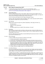
RF & Tissue Processor Board, RFT
NOTE:
The RF & Tissue Processor Board (RFT) is only used in Front-End Rack version 1.
In units with Front-End Rack version 2, the RFI board replaces the functionality of this board,
see:
5-3-21 "Radio Frequency Interface Board, RFI" on page 5-61
.
5-3-18-1
General Description
The RF & Tissue Processor board receives digitized ultrasound signals from the Beam Formers. It
extracts Tissue Data, Spectrum Data and IQ & Color Data from the digital data stream on its input and
it also performs RF filtering and different types of Tissue Processing.
The result is sent via the PipeLink bus to the Spectrum Doppler Processor.
Both type of data and what data samples (RF_MODE) to use are communicated to the RFT board from
the Front-End Controller board (over the Front-End Bus).
5-3-18-1-1
RF Processing
Different types of RF processing can be performed depending on later usage of the data; e.g.:
•
RF Demodulation
•
Digital Time Gain Compensation
•
Filtering
•
Decimation (data that are not needed for the processing, is removed)
5-3-18-1-2
Data Buffer
After RF filtering, the data is written into different sliding ring buffers, dedicated the different types of
data. While data is written into the buffers sample by sample in vectors, multiple samples from the same
range (depth) can be read out.
Both input addressing (start and length) and output addressing (through output events) are controlled
by the Front-End Controller board.
5-3-18-1-3
Tissue Processing
A number of different tissue processes are performed on this board:
1.) First the signal amplitude is obtained by
detection
.
2.) Then the data is compressed to attenuate the strong signals and amplify the low level echoes.
3.) After compression,
Zone Stitching
is performed. Zone Stitching is used to combine the (transmit)
focal zones from different vectors into one vector by weighting the zone transitions, and does only
apply to phased/linear array probes where multiple vectors can be collected in the same direction.
For M-Mode,
peak detection
and
edge enhancement
is implemented.
4.) Finally an offset can be added to the signal and clipping is performed.
5.) The tissue data is then tagged, and sent on to the Image Port board.
5-3-18-1-4
Color Flow Processing
No Color Flow processing is performed here, except for the RF demodulation previously mentioned.
The data used for Color Flow is tagged with the appropriate headers and tails and routed through an
output multiplexer, via the Image Port to the Back-End Processor (BEP).
In addition to RF demodulation, a variable digital high pass filter is implemented on the RFT board.The
purpose of this filter is to remove strong low frequency signals returning from wall motion, valves and
leaflets. The filtering is performed by an on-board DSP (Digital Signal Processor). Data is then tagged
and sent to the Spectrum Doppler Processor board.
Содержание Vivid 7
Страница 1: ...GE Healthcare Operating Documentation Vivid 7 Service Manual Part Number FC091194 Revision 11...
Страница 2: ......
Страница 9: ...GE HEALTHCARE DIRECTION FC091194 REVISION 11 VIVID 7 SERVICE MANUAL vii JA ZH CN KO...
Страница 37: ...GE HEALTHCARE DIRECTION FC091194 REVISION 11 VIVID 7 SERVICE MANUAL xxxv Site Log 10 27 Index Index 1...
Страница 38: ...GE HEALTHCARE DIRECTION FC091194 REVISION 11 VIVID 7 SERVICE MANUAL xxxvi...
Страница 856: ...GE HEALTHCARE DIRECTION FC091194 REVISION 11 VIVID 7 SERVICE MANUAL Index 8...
Страница 857: ......

