


GE H
EALTHCARE
D
IRECTION
FC091194, R
EVISION
11
V
IVID
7 S
ERVICE
M
ANUAL
Chapter 1 - Introduction
1 - 51
1-5-18
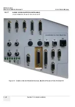
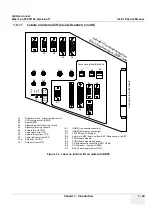
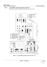
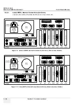
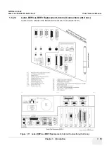
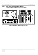
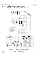
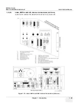
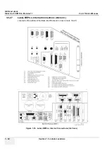
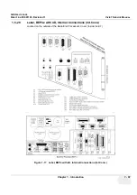
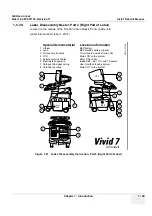
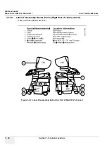
Label, Internal Connections (Int.Conn.)
Located on the outside of the Front-End Card Rack (FEP1) Cover (inside Vivid 7). Different versions of
the label have been used since production start.
Figure 1-6 Label on FEP1, Internal Connections
K1
K2
K3
Cable and Connector numbering and naming system used:
IIO
= Internal IO module
EIO
= External IO module
BEP
= Backend Processor
FEP
= Frontend Processor
ACP
= AC controller module
ACD
= AC distribution box
ACT
= AC isolation transformer module
BEPIO
= IO module on the BEP
Axx :
connectors on IIO with other connections than the BEP
Bxx :
connectors on IIO that are connected to BEP
Cxx :
connectors on BEP, except for the BEPIO
Dxx :
connectors on BEPIO
Exx :
connector on the BEP power supply
Fxx :
connectors on ACP
Gxx :
connectors on FEP
Hxx :
external accesable connectors (Doppler probe)
Kxx :
connectors on MODEM
Mxx :
connectors on ACT
Nxx :
connectors on ACD
Lxx :
connectors on EIO
External IO module
6
9
1
5
M
1
4
6
9
1
5
M
Analogue
phone
Connect
to InSite
MODEM
RS-232
Connect
to InSite
MODEM
Service
use ONLY
(remote
power on/off
control)
L1
L2
L3
BF-64
BF-64
FEC-2
RFT-1
SDP-2
IMP
Not use
d
DC-power
supply
T
X-pow
er
su
pply
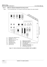
Board location in Front End Processor (FEP)
Monito
r
Peripheral
s
Mode
m
Back E
n
d
Processo
r
Front E
n
d
Rack
115V
115V
or
230V
230V
230V
230V
From Isolation
transformer
230V
115V
WARNING !
Live Voltage inside,
do not open.
AC power control module
To Isolation
transformer
115V or 230V inlet
voltage selection
Voltage Selection
on Peripherals
115
V =
100
-120
V
230
V =
220
-240
V
(½ o
r 2 t
ime
s in
let
volt
age
)
H1
G1
F1
F2
F3
F4
F5
F6
F7
F8
F9
Isolation
transformer
module
M1
69
15
M
230V
115V
Fa
n
co
nt
ro
l
81
15
9
F
A13
81
15
9
F
A12
1
13
14
25
M
A16
18
91
5
M
A15
69
1
5
M
A14
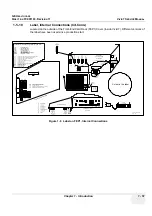
A12
Spare power (future option)
A13
Power to 3D box (future option)
A14
AC power control
A15
Signals to rotation adapter (future option)
A16
Signals to 3D box (future option)
connector
to EIO
1
25
A
F
P30
C
onnec
tor t
o
m
ot
herboar
d
P31
P32
IIO s
een
from
FEP
side
Part no. : FB314746
Rev. : 05
60,0
Cable to
C15
Modem
MT5634ZBA
Modem
power
supply
K4
G4
G3
G2
AC
Distribution
box
N1
N2
N3
N4
N5
RX-128
Relay boar
d
M
F
L4
L5
L6
L7
L8
L9
L10
L11
L12
L13
L14
L15
L16
L17
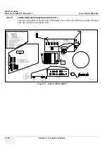
External IO module
(Front view)
L4:
Audio out (right)
L5:
Audio out (left)
L6:
Trig out
L7:
Foot switch
L8:
Serial port
L9:
Remote expose #1
L10:
Remote expose #2
L11:
Analog modem
L12:
Composite video output
L13:
B&W video output
L14:
S-Video output
L15:
SVGA output
L16:
USB
L17:
Ethernet
RESET
TX-12
8
Cutout in the label
Содержание Vivid 7
Страница 1: ...GE Healthcare Operating Documentation Vivid 7 Service Manual Part Number FC091194 Revision 11...
Страница 2: ......
Страница 9: ...GE HEALTHCARE DIRECTION FC091194 REVISION 11 VIVID 7 SERVICE MANUAL vii JA ZH CN KO...
Страница 37: ...GE HEALTHCARE DIRECTION FC091194 REVISION 11 VIVID 7 SERVICE MANUAL xxxv Site Log 10 27 Index Index 1...
Страница 38: ...GE HEALTHCARE DIRECTION FC091194 REVISION 11 VIVID 7 SERVICE MANUAL xxxvi...
Страница 856: ...GE HEALTHCARE DIRECTION FC091194 REVISION 11 VIVID 7 SERVICE MANUAL Index 8...
Страница 857: ......


