GE H
EALTHCARE
D
IRECTION
FQ091013, R
EVISION
1
V
IVID
I
N
AND
V
IVID
Q
N S
ERVICE
M
ANUAL
Chapter 5 - Components and Function (Theory)
5-17
Each TR32 Board has 32 channels and includes a 32-channel Digital Beam Former
(consisting of one
FOC32 ASIC).
Inputs are 32 probe lines that have gone through aperture selection, performed in the P&M Board.
Outputs are MLA0 and MLA1 digital buses from the Beam Former and CW output lines to the
Analog CW BF.
The MLA output bus of TR32B is connected to the MLA input bus of TR32A, giving a 64-channel BF on
the MLA output.
All required control, memory and clocks for the two TR32 Boards reside in the RFI Board.
The two TR32 Boards are linked together in parallel. The way in which they operate depends upon the
probe currently in use, and also on the current type of Transmit/Receive mode.
Transmit/Receive modes can be divided into two types, as shown in the following examples:
•
CW Mode
-
half the channels
transmit
signals, and half the channels
receive
signals, simultaneously.
•
2D Mode
-
signals are propagated between the channels; there is a specific
time delay between
transmit
and
receive -
data is then interpolated
in accordance with the delay, and the image is created.
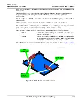
The TR32 Boards are connected to the RFI Board by stacked connectors, as shown
.
Figure 5-13 TR32 Board - Stacked Connectors
Probe & MUX
Connector
TR32 1 & 2
Stacked
Connectors
RFI
Connectors
Содержание FL000090
Страница 2: ......
Страница 30: ...GE HEALTHCARE DIRECTION FQ091013 REVISION 1 VIVID I N AND VIVID Q N SERVICE MANUAL xxviii ...
Страница 739: ......


