


GE Multilin
L30 Line Current Differential System
3-23
3 HARDWARE
3.2 WIRING
3
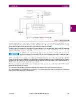
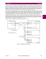
To minimize errors from noise, the use of shielded twisted pair wire is recommended. Correct polarity must also be
observed. For instance, the relays must be connected with all RS485 “+” terminals connected together, and all RS485 “–”
terminals connected together. Though data is transmitted over a two-wire twisted pair, all RS485 devices require a shared
reference, or common voltage. This common voltage is implied to be a power supply common. Some systems allow the
shield (drain wire) to be used as common wire and to connect directly to the L30 COM terminal (#3); others function cor-
rectly only if the common wire is connected to the L30 COM terminal, but insulated from the shield.
To avoid loop currents, ground the shield at only one point. If other system considerations require the shield to be grounded
at more than one point, install resistors (typically 100 ohms) between the shield and ground at each grounding point. Each
relay needs to be daisy-chained to the next one in the link. A maximum of 32 relays can be connected in this manner with-
out exceeding driver capability. For larger systems, additional serial channels must be added. It is also possible to use com-
mercially available repeaters to have more than 32 relays on a single channel. Avoid star or stub connections entirely.
Lightning strikes and ground surge currents can cause large momentary voltage differences between remote ends of the
communication link. For this reason, surge protection devices are internally provided at both communication ports. An iso-
lated power supply with an optocoupled data interface also acts to reduce noise coupling. To ensure maximum reliability, all
equipment should have similar transient protection devices installed.
Terminate both ends of the RS485 circuit with an impedance as shown below.
Figure 3–25: RS485 SERIAL CONNECTION
Содержание L30
Страница 10: ...x L30 Line Current Differential System GE Multilin TABLE OF CONTENTS ...
Страница 30: ...1 20 L30 Line Current Differential System GE Multilin 1 5 USING THE RELAY 1 GETTING STARTED 1 ...
Страница 58: ...2 28 L30 Line Current Differential System GE Multilin 2 4 SPECIFICATIONS 2 PRODUCT DESCRIPTION 2 ...
Страница 126: ...4 30 L30 Line Current Differential System GE Multilin 4 3 FACEPLATE INTERFACE 4 HUMAN INTERFACES 4 ...
Страница 370: ...5 244 L30 Line Current Differential System GE Multilin 5 10 TESTING 5 SETTINGS 5 ...
Страница 396: ...6 26 L30 Line Current Differential System GE Multilin 6 5 PRODUCT INFORMATION 6 ACTUAL VALUES 6 ...
Страница 450: ...10 10 L30 Line Current Differential System GE Multilin 10 4 INSTANTANEOUS ELEMENTS 10 APPLICATION OF SETTINGS 10 ...
Страница 464: ...A 10 L30 Line Current Differential System GE Multilin A 1 PARAMETER LISTS APPENDIX A A ...
Страница 600: ...C 30 L30 Line Current Differential System GE Multilin C 7 LOGICAL NODES APPENDIX C C ...
Страница 610: ...D 10 L30 Line Current Differential System GE Multilin D 1 IEC 60870 5 104 APPENDIX D D ...
Страница 622: ...E 12 L30 Line Current Differential System GE Multilin E 2 DNP POINT LISTS APPENDIX E E ...
Страница 634: ...F 12 L30 Line Current Differential System GE Multilin F 3 WARRANTY APPENDIX F F ...
Страница 644: ...x L30 Line Current Differential System GE Multilin INDEX ...