


GE Multilin
L30 Line Current Differential System
5-225
5 SETTINGS
5.8 INPUTS AND OUTPUTS
5
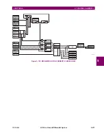
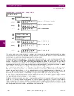
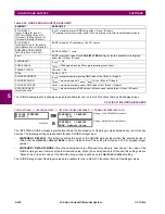
Write the following FlexLogic equation (EnerVista UR Setup example shown):
Both timers (Timer 1 and Timer 2) should be set to 20 ms pickup and 0 ms dropout.
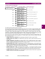
Program the Latching Outputs by making the following changes in the
SETTINGS
INPUTS/OUTPUTS
CONTACT OUT-
PUTS
CONTACT OUTPUT H1a
and
CONTACT OUTPUT H1c
menus (assuming an H4L module):
OUTPUT H1a OPERATE:
“
VO1
”
OUTPUT H1c OPERATE:
“
VO2
”
OUTPUT H1a RESET:
“
VO4
”
OUTPUT H1c RESET:
“
VO3
”
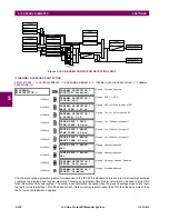
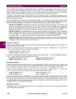
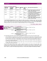
Application Example 4:
A latching contact H1a is to be controlled from a single virtual output VO1. The contact should stay closed as long as VO1
is high, and should stay opened when VO1 is low. Program the relay as follows.
Write the following FlexLogic equation (EnerVista UR Setup example shown):
Program the Latching Outputs by making the following changes in the
SETTINGS
INPUTS/OUTPUTS
CONTACT OUT-
PUTS
CONTACT OUTPUT H1a
menu (assuming an H4L module):
OUTPUT H1a OPERATE:
“
VO1
”
OUTPUT H1a RESET:
“
VO2
”
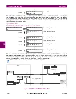
5.8.4 VIRTUAL OUTPUTS
PATH: SETTINGS
INPUTS/OUTPUTS
VIRTUAL OUTPUTS
VIRTUAL OUTPUT 1(96)
There are 96 virtual outputs that may be assigned via FlexLogic. If not assigned, the output will be forced to ‘OFF’ (Logic 0).
An ID may be assigned to each virtual output. Virtual outputs are resolved in each pass through the evaluation of the Flex-
Logic equations. Any change of state of a virtual output can be logged as an event if programmed to do so.
For example, if Virtual Output 1 is the trip signal from FlexLogic and the trip relay is used to signal events, the settings
would be programmed as follows:
VIRTUAL OUTPUT 1
VIRTUAL OUTPUT 1 ID
Virt Op 1
Range: Up to 12 alphanumeric characters
MESSAGE
VIRTUAL OUTPUT 1
EVENTS: Disabled
Range: Disabled, Enabled
Содержание L30
Страница 10: ...x L30 Line Current Differential System GE Multilin TABLE OF CONTENTS ...
Страница 30: ...1 20 L30 Line Current Differential System GE Multilin 1 5 USING THE RELAY 1 GETTING STARTED 1 ...
Страница 58: ...2 28 L30 Line Current Differential System GE Multilin 2 4 SPECIFICATIONS 2 PRODUCT DESCRIPTION 2 ...
Страница 126: ...4 30 L30 Line Current Differential System GE Multilin 4 3 FACEPLATE INTERFACE 4 HUMAN INTERFACES 4 ...
Страница 370: ...5 244 L30 Line Current Differential System GE Multilin 5 10 TESTING 5 SETTINGS 5 ...
Страница 396: ...6 26 L30 Line Current Differential System GE Multilin 6 5 PRODUCT INFORMATION 6 ACTUAL VALUES 6 ...
Страница 450: ...10 10 L30 Line Current Differential System GE Multilin 10 4 INSTANTANEOUS ELEMENTS 10 APPLICATION OF SETTINGS 10 ...
Страница 464: ...A 10 L30 Line Current Differential System GE Multilin A 1 PARAMETER LISTS APPENDIX A A ...
Страница 600: ...C 30 L30 Line Current Differential System GE Multilin C 7 LOGICAL NODES APPENDIX C C ...
Страница 610: ...D 10 L30 Line Current Differential System GE Multilin D 1 IEC 60870 5 104 APPENDIX D D ...
Страница 622: ...E 12 L30 Line Current Differential System GE Multilin E 2 DNP POINT LISTS APPENDIX E E ...
Страница 634: ...F 12 L30 Line Current Differential System GE Multilin F 3 WARRANTY APPENDIX F F ...
Страница 644: ...x L30 Line Current Differential System GE Multilin INDEX ...