


GE Multilin
L30 Line Current Differential System
5-99
5 SETTINGS
5.4 SYSTEM SETUP
5
The Value of the Nominal Frequency of the chassis is instantiated as a DO in LPHD of LD1. The value is named HzNom
and is an Integer Status (INS).
The value of the nominal system frequency is stored within the CID file created by URPC.
The UR also supports the option to apply no filtering to the synchrophasors. If no filtering is applied (PMU Class = None),
according to the standard the ClcMth attribute will be PRES. The semantic of the ClcMth used is not carried in the individual
DO and so it is recommended that one of letters of the prefix on the instantiated LNs be set to “P” or “M” accordingly in
order to differentiate. For version 7.0 only FCDA data is supported. The
Implementation by Model Number
table, see
above
,
describes the maximum size of each PMU data set for version 7.0 using FCDA data (non-structured data).
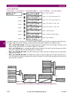
EXAMPLE: PROTECTION SYNCHROPHASORS DATA SET WITH REPORTING RATE 60 FRAMES/SECOND
This example gives the protection synchrophasors data set with a reporting rate of 60 frames per second (P60MMXU1).
See figure above, Logical Nodes Supported in Each Logical Device. This data or list of items, see figure below, is not yet
exposed to the client but available to be mapped by the user into a selected aggregator or aggregators dataset. The logical
device name – LDName - of each PMU LD will be a 64 character user setting. The C37.118 STN and IDCode is to be
mapped as a concatenated value in the (d)escription field of LPL CDC of the NamPlt DO in LLN0. The mapping is imple-
mented as STN-IDCode(text string).
From each PMU the user selects the phasor information of interest that is mapped into the selected aggregator datset(s).
For version 7.0 only FCDA data is supported.
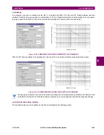
Figure 5–38: DATA SET CREATED FROM USER SELECTED INTERNAL ITEMS
Содержание L30
Страница 10: ...x L30 Line Current Differential System GE Multilin TABLE OF CONTENTS ...
Страница 30: ...1 20 L30 Line Current Differential System GE Multilin 1 5 USING THE RELAY 1 GETTING STARTED 1 ...
Страница 58: ...2 28 L30 Line Current Differential System GE Multilin 2 4 SPECIFICATIONS 2 PRODUCT DESCRIPTION 2 ...
Страница 126: ...4 30 L30 Line Current Differential System GE Multilin 4 3 FACEPLATE INTERFACE 4 HUMAN INTERFACES 4 ...
Страница 370: ...5 244 L30 Line Current Differential System GE Multilin 5 10 TESTING 5 SETTINGS 5 ...
Страница 396: ...6 26 L30 Line Current Differential System GE Multilin 6 5 PRODUCT INFORMATION 6 ACTUAL VALUES 6 ...
Страница 450: ...10 10 L30 Line Current Differential System GE Multilin 10 4 INSTANTANEOUS ELEMENTS 10 APPLICATION OF SETTINGS 10 ...
Страница 464: ...A 10 L30 Line Current Differential System GE Multilin A 1 PARAMETER LISTS APPENDIX A A ...
Страница 600: ...C 30 L30 Line Current Differential System GE Multilin C 7 LOGICAL NODES APPENDIX C C ...
Страница 610: ...D 10 L30 Line Current Differential System GE Multilin D 1 IEC 60870 5 104 APPENDIX D D ...
Страница 622: ...E 12 L30 Line Current Differential System GE Multilin E 2 DNP POINT LISTS APPENDIX E E ...
Страница 634: ...F 12 L30 Line Current Differential System GE Multilin F 3 WARRANTY APPENDIX F F ...
Страница 644: ...x L30 Line Current Differential System GE Multilin INDEX ...