


5-176
L30 Line Current Differential System
GE Multilin
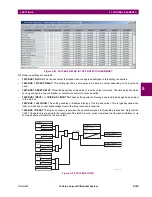
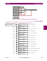
5.6 GROUPED ELEMENTS
5 SETTINGS
5
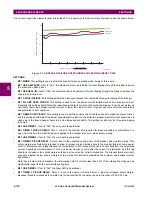
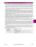
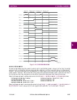
Figure 5–80: INVERSE TIME UNDERVOLTAGE CURVES
At 0% of pickup, the operating time equals the UNDERVOLTAGE DELAY setting.
b) PHASE UNDERVOLTAGE
(ANSI 27P, IEC PTUV)
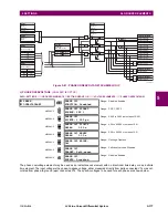
PATH: SETTINGS
GROUPED ELEMENTS
SETTING GROUP 1(6)
VOLTAGE ELEMENTS
PHASE UNDERVOLTAGE1(3)
This element may be used to give a desired time-delay operating characteristic versus the applied fundamental voltage
(phase-to-ground or phase-to-phase for wye VT connection, or phase-to-phase for delta VT connection) or as a definite
time element. The element resets instantaneously if the applied voltage exceeds the dropout voltage. The delay setting
selects the minimum operating time of the phase undervoltage. The minimum voltage setting selects the operating voltage
below which the element is blocked (a setting of “0” will allow a dead source to be considered a fault condition).
PHASE
UNDERVOLTAGE1
PHASE UV1
FUNCTION: Disabled
Range: Disabled, Enabled
MESSAGE
PHASE UV1 SIGNAL
SOURCE: SRC 1
Range: SRC 1, SRC 2
MESSAGE
PHASE UV1 MODE:
Phase to Ground
Range: Phase to Ground, Phase to Phase
MESSAGE
PHASE UV1
PICKUP: 1.000 pu
Range: 0.000 to 3.000 pu in steps of 0.001
MESSAGE
PHASE UV1
CURVE: Definite Time
Range: Definite Time, Inverse Time
MESSAGE
PHASE UV1
DELAY: 1.00
s
Range: 0.00 to 600.00 s in steps of 0.01
MESSAGE
PHASE UV1 MINIMUM
VOLTAGE: 0.100 pu
Range: 0.000 to 3.000 pu in steps of 0.001
MESSAGE
PHASE UV1 BLOCK:
Off
Range: FlexLogic operand
MESSAGE
PHASE UV1
TARGET: Self-reset
Range: Self-reset, Latched, Disabled
MESSAGE
PHASE UV1
EVENTS: Disabled
Range: Disabled, Enabled
842788A1.CDR
% of voltage pickup
T
ime
(seconds)
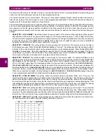
NOTE
Содержание L30
Страница 10: ...x L30 Line Current Differential System GE Multilin TABLE OF CONTENTS ...
Страница 30: ...1 20 L30 Line Current Differential System GE Multilin 1 5 USING THE RELAY 1 GETTING STARTED 1 ...
Страница 58: ...2 28 L30 Line Current Differential System GE Multilin 2 4 SPECIFICATIONS 2 PRODUCT DESCRIPTION 2 ...
Страница 126: ...4 30 L30 Line Current Differential System GE Multilin 4 3 FACEPLATE INTERFACE 4 HUMAN INTERFACES 4 ...
Страница 370: ...5 244 L30 Line Current Differential System GE Multilin 5 10 TESTING 5 SETTINGS 5 ...
Страница 396: ...6 26 L30 Line Current Differential System GE Multilin 6 5 PRODUCT INFORMATION 6 ACTUAL VALUES 6 ...
Страница 450: ...10 10 L30 Line Current Differential System GE Multilin 10 4 INSTANTANEOUS ELEMENTS 10 APPLICATION OF SETTINGS 10 ...
Страница 464: ...A 10 L30 Line Current Differential System GE Multilin A 1 PARAMETER LISTS APPENDIX A A ...
Страница 600: ...C 30 L30 Line Current Differential System GE Multilin C 7 LOGICAL NODES APPENDIX C C ...
Страница 610: ...D 10 L30 Line Current Differential System GE Multilin D 1 IEC 60870 5 104 APPENDIX D D ...
Страница 622: ...E 12 L30 Line Current Differential System GE Multilin E 2 DNP POINT LISTS APPENDIX E E ...
Страница 634: ...F 12 L30 Line Current Differential System GE Multilin F 3 WARRANTY APPENDIX F F ...
Страница 644: ...x L30 Line Current Differential System GE Multilin INDEX ...