


9-18
L30 Line Current Differential System
GE Multilin
9.2 OPERATING CONDITION CHARACTERISTICS
9 THEORY OF OPERATION
9
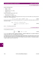
9.2.2 TRIP DECISION EXAMPLE
Assume the following settings:
•
Slope 1:
S
1
= 10%
•
Slope 2:
S
2
= 10%
•
Breakpoint: BP = 5 pu secondary
•
Pickup:
P
= 0.5 pu
Assume the following local and remote currents:
•
Local current:
I
local
= 4.0 pu
0°
•
Remote current:
I
remote
= 0.8 pu
180°
The assumed condition is a radial line with a high resistance fault, with the source at the local end only, and through a resis-
tive load current. The operating current is:
(EQ 9.34)
Since the current at both ends is less than the breakpoint value of 5.0, the equation for two-terminal mode is used to calcu-
late restraint as follows.
(EQ 9.35)
where = 0, assuming a pure sine wave.
9.2.3 TRIP DECISION TEST
The trip condition is shown below.
(EQ 9.36)
The use of the
CURRENT DIFF PICKUP
,
CURRENT DIFF RESTRAINT 1
,
CURRENT DIFF RESTRAINT 2
, and
CURRENT DIFF BREAK PT
settings are discussed in the
Current differential
section of chapter 5.
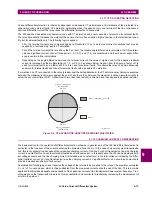
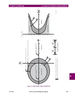
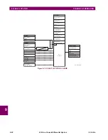
The following figure shows how the L30 settings affect the restraint characteristics. The local and remote currents are 180°
apart, which represents an external fault. The breakpoint between the two slopes indicates the point where the restraint
area is becoming wider to override uncertainties from CT saturation, fault noise, harmonics, etc. Increasing the slope per-
centage increases the width of the restraint area.
I
op
2
I
_L
I
_R
2
4.0 0
0.8 180
2
10.24
I
Rest
2
2
S
1
2
I
_L
2
2
S
1
2
I
_R
2
2
P
2
2
0.1
2
4
2
2
0.1
2
0.8
2
2
0.5
2
0
0.8328
I
Op
2
I
Rest
2
------------
1
10.24
0.8328
------------------
12.3 1
Trip
Содержание L30
Страница 10: ...x L30 Line Current Differential System GE Multilin TABLE OF CONTENTS ...
Страница 30: ...1 20 L30 Line Current Differential System GE Multilin 1 5 USING THE RELAY 1 GETTING STARTED 1 ...
Страница 58: ...2 28 L30 Line Current Differential System GE Multilin 2 4 SPECIFICATIONS 2 PRODUCT DESCRIPTION 2 ...
Страница 126: ...4 30 L30 Line Current Differential System GE Multilin 4 3 FACEPLATE INTERFACE 4 HUMAN INTERFACES 4 ...
Страница 370: ...5 244 L30 Line Current Differential System GE Multilin 5 10 TESTING 5 SETTINGS 5 ...
Страница 396: ...6 26 L30 Line Current Differential System GE Multilin 6 5 PRODUCT INFORMATION 6 ACTUAL VALUES 6 ...
Страница 450: ...10 10 L30 Line Current Differential System GE Multilin 10 4 INSTANTANEOUS ELEMENTS 10 APPLICATION OF SETTINGS 10 ...
Страница 464: ...A 10 L30 Line Current Differential System GE Multilin A 1 PARAMETER LISTS APPENDIX A A ...
Страница 600: ...C 30 L30 Line Current Differential System GE Multilin C 7 LOGICAL NODES APPENDIX C C ...
Страница 610: ...D 10 L30 Line Current Differential System GE Multilin D 1 IEC 60870 5 104 APPENDIX D D ...
Страница 622: ...E 12 L30 Line Current Differential System GE Multilin E 2 DNP POINT LISTS APPENDIX E E ...
Страница 634: ...F 12 L30 Line Current Differential System GE Multilin F 3 WARRANTY APPENDIX F F ...
Страница 644: ...x L30 Line Current Differential System GE Multilin INDEX ...