


GE Multilin
L30 Line Current Differential System
5-79
5 SETTINGS
5.4 SYSTEM SETUP
5
•
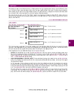
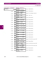
Channel asymmetry prior to losing the GPS time reference
. This value is measured by the L30 and a user-pro-
grammable threshold is applied to it. The corresponding FlexLogic operands are produced if the asymmetry is
above the threshold (
87L DIFF MAX 1 ASYM
and
87L DIFF 2 MAX ASYM
). These operands can be latched in Flex-
Logic and combined with other factors to decide, upon GPS loss, if the relays continue to compensate using the
memorized correction. Typically, one may decide to keep compensating if the pre-existing asymmetry was low.
•
Change in the round trip travel time
. This value is measured by the L30 and a user-programmable threshold
applied to it. The corresponding FlexLogic operands are produced if the delta change is above the threshold (
87L
DIFF 1 TIME CHNG
and
87L DIFF 2 TIME CHNG
). These operands can be latched in FlexLogic and combined with
other factors to decide, upon GPS loss, if the relays continue to compensate using the memorized correction. Typ-
ically, one may decide to disable compensation if the round trip time changes.
•
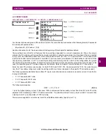
BLOCK GPS TIME REF:
This setting signals to the L30 that the time reference is not valid. The time reference may be
not accurate due to problems with the GPS receiver. The user must to be aware of the case when a GPS satellite
receiver loses its satellite signal and reverts to its own calibrated crystal oscillator. In this case, accuracy degrades in
time and may eventually cause relay misoperation. Verification from the manufacturer of receiver accuracy not worse
than 250
s and the presence of an alarm contact indicating loss of the satellite signal is strongly recommended. If the
time reference accuracy cannot be guaranteed, it should be relayed to the L30 via contact inputs and GPS compensa-
tion effectively blocked using the contact position in conjunction with the
BLOCK GPS TIME REF
setting. This setting is
typically a signal from the GPS receiver signaling problems or time inaccuracy.
Some GPS receivers can supply erroneous IRIG-B signals during power-up and before locking to satellites. If the
receiver’s failsafe contact opens during power-up (allowing for an erroneous IRIG-B signal), then set a dropout delay
up to 15 minutes (depending on GPS receiver specifications) to the failsafe contact via FlexLogic to prevent incorrect
relay response.
•
MAX CHNL ASYMMETRY:
This setting detects excessive channel asymmetry. The same threshold is applied to both
the channels, while the following per-channel FlexLogic operands are generated:
87L DIFF 1 MAX ASYM
and
87L DIFF 2
MAX ASYM
. These operands can be used to alarm on problems with communication equipment and/or to decide
whether channel asymmetry compensation remains in operation should the GPS-based time reference be lost. Chan-
nel asymmetry is measured if both terminals of a given channel have valid time reference.
If the memorized asymmetry value is much greater than expected (indicating a significant problem with GPS clock tim-
ing), then this operand can be also used to block GPS compensation, forcing the relay to use the memorized asymme-
try value.
•
ROUND TRIP TIME CHANGE:
This setting detects changes in round trip time. This threshold is applied to both chan-
nels, while the
87L DIFF 1 TIME CHNG
and
87L DIFF 2 TIME CHNG ASYM
per-channel FlexLogic operands are generated.
These operands can be used to alarm on problems with communication equipment and/or to decide whether channel
asymmetry compensation remains in operation should the GPS-based time reference be lost.
•
LOCAL GPS TROUBLE
: This signal is On when any of the following conditions are present:
•
The BCS selection is none or SNTP
•
The BCS selection is IRIG-B and the IRIG-B SIGNAL TYPE setting is Amplitude Modulated
•
The RTC and/or the synchrophasor clock are not synchronized to the selected synchronizing source. This can
possibly occur on power up, when transferring between sources, and when the selected source's holdover timer
times out.
•
The quality bits in the messages from the a PTP source used for synchronizing indicate worst-case error greater
than 250 µs, or accuracy less than 250 µs, or unknown accuracy/error (that is, not locked to an international time
standard). Apply 2 security counts (2 seconds) to both set and reset of this operand when change is based on
accuracy. There is no corresponding quality test for IRIG-B sources here.
Содержание L30
Страница 10: ...x L30 Line Current Differential System GE Multilin TABLE OF CONTENTS ...
Страница 30: ...1 20 L30 Line Current Differential System GE Multilin 1 5 USING THE RELAY 1 GETTING STARTED 1 ...
Страница 58: ...2 28 L30 Line Current Differential System GE Multilin 2 4 SPECIFICATIONS 2 PRODUCT DESCRIPTION 2 ...
Страница 126: ...4 30 L30 Line Current Differential System GE Multilin 4 3 FACEPLATE INTERFACE 4 HUMAN INTERFACES 4 ...
Страница 370: ...5 244 L30 Line Current Differential System GE Multilin 5 10 TESTING 5 SETTINGS 5 ...
Страница 396: ...6 26 L30 Line Current Differential System GE Multilin 6 5 PRODUCT INFORMATION 6 ACTUAL VALUES 6 ...
Страница 450: ...10 10 L30 Line Current Differential System GE Multilin 10 4 INSTANTANEOUS ELEMENTS 10 APPLICATION OF SETTINGS 10 ...
Страница 464: ...A 10 L30 Line Current Differential System GE Multilin A 1 PARAMETER LISTS APPENDIX A A ...
Страница 600: ...C 30 L30 Line Current Differential System GE Multilin C 7 LOGICAL NODES APPENDIX C C ...
Страница 610: ...D 10 L30 Line Current Differential System GE Multilin D 1 IEC 60870 5 104 APPENDIX D D ...
Страница 622: ...E 12 L30 Line Current Differential System GE Multilin E 2 DNP POINT LISTS APPENDIX E E ...
Страница 634: ...F 12 L30 Line Current Differential System GE Multilin F 3 WARRANTY APPENDIX F F ...
Страница 644: ...x L30 Line Current Differential System GE Multilin INDEX ...