


C-14
L30 Line Current Differential System
GE Multilin
C.5 IEC 61850 IMPLEMENTATION VIA ENERVISTA UR SETUP
APPENDIX C
C
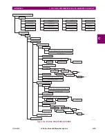
The root file structure of an ICD file is illustrated below.
Figure 0–2: ICD FILE STRUCTURE, SCL (ROOT) NODE
The
Header
node identifies the ICD file and its version, and specifies options for the mapping of names to signals
The
Communication
node describes the direct communication connection possibilities between logical nodes by means of
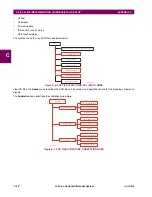
logical buses (sub-networks) and IED access ports. The communication section is structured as follows.
Figure 0–3: ICD FILE STRUCTURE, COMMUNICATIONS NODE
The
SubNetwork
node contains all access points which can (logically) communicate with the sub-network protocol and
without the intervening router. The
ConnectedAP
node describes the IED access point connected to this sub-network. The
Address
node contains the address parameters of the access point. The
GSE
node provides the address element for stat-
ing the control block related address parameters, where
IdInst
is the instance identification of the logical device within the
IED on which the control block is located, and
cbName
is the name of the control block.
The
IED
node describes the (pre-)configuration of an IED: its access points, the logical devices, and logical nodes instanti-
ated on it. Furthermore, it defines the capabilities of an IED in terms of communication services offered and, together with
its
LNType
, instantiated data (DO) and its default or configuration values. There should be only one IED section in an ICD
since it only describes one IED.
842795A1.CDR
SCL
Header (id, version, revision, toolID, nameStructure)
Communication
IED (name, type, manufacture, configVersion)
DataTypeTemplates
842796A1.CDR
Communication
SubNetwork (name)
ConnectedAP (iedName, apName)
Address
GSE (IdInst, cbName)
P (type)
Other P elements
Text
Address
P (type)
Other P elements
Text
Other GSE elements
Содержание L30
Страница 10: ...x L30 Line Current Differential System GE Multilin TABLE OF CONTENTS ...
Страница 30: ...1 20 L30 Line Current Differential System GE Multilin 1 5 USING THE RELAY 1 GETTING STARTED 1 ...
Страница 58: ...2 28 L30 Line Current Differential System GE Multilin 2 4 SPECIFICATIONS 2 PRODUCT DESCRIPTION 2 ...
Страница 126: ...4 30 L30 Line Current Differential System GE Multilin 4 3 FACEPLATE INTERFACE 4 HUMAN INTERFACES 4 ...
Страница 370: ...5 244 L30 Line Current Differential System GE Multilin 5 10 TESTING 5 SETTINGS 5 ...
Страница 396: ...6 26 L30 Line Current Differential System GE Multilin 6 5 PRODUCT INFORMATION 6 ACTUAL VALUES 6 ...
Страница 450: ...10 10 L30 Line Current Differential System GE Multilin 10 4 INSTANTANEOUS ELEMENTS 10 APPLICATION OF SETTINGS 10 ...
Страница 464: ...A 10 L30 Line Current Differential System GE Multilin A 1 PARAMETER LISTS APPENDIX A A ...
Страница 600: ...C 30 L30 Line Current Differential System GE Multilin C 7 LOGICAL NODES APPENDIX C C ...
Страница 610: ...D 10 L30 Line Current Differential System GE Multilin D 1 IEC 60870 5 104 APPENDIX D D ...
Страница 622: ...E 12 L30 Line Current Differential System GE Multilin E 2 DNP POINT LISTS APPENDIX E E ...
Страница 634: ...F 12 L30 Line Current Differential System GE Multilin F 3 WARRANTY APPENDIX F F ...
Страница 644: ...x L30 Line Current Differential System GE Multilin INDEX ...