


GE Multilin
L30 Line Current Differential System
5-205
5 SETTINGS
5.7 CONTROL ELEMENTS
5
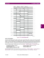
As long as the current through the voltage monitor is above a threshold (see technical specifications for form-A), the “Cont
Op 1 VOn” FlexLogic operand will be set (for contact input 1 – corresponding operands exist for each contact output). If the
output circuit has a high resistance or the DC current is interrupted, the trickle current will drop below the threshold and the
“Cont Op 1 VOff” FlexLogic operand will be set. Consequently, the state of these operands can be used as indicators of the
integrity of the circuits in which form-A contacts are inserted.
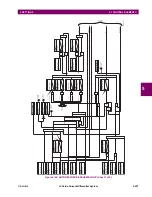
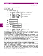
EXAMPLE 1: BREAKER TRIP CIRCUIT INTEGRITY MONITORING
In many applications it is desired to monitor the breaker trip circuit integrity so problems can be detected before a trip oper-
ation is required. The circuit is considered to be healthy when the voltage monitor connected across the trip output contact
detects a low level of current, well below the operating current of the breaker trip coil. If the circuit presents a high resis-
tance, the trickle current will fall below the monitor threshold and an alarm would be declared.
In most breaker control circuits, the trip coil is connected in series with a breaker auxiliary contact which is open when the
breaker is open (see diagram below). To prevent unwanted alarms in this situation, the trip circuit monitoring logic must
include the breaker position.
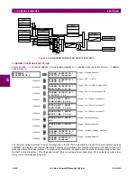
Figure 5–99: TRIP CIRCUIT EXAMPLE 1
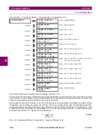
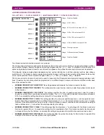
Assume the output contact H1 is a trip contact. Using the contact output settings, this output will be given an ID name; for
example, “Cont Op 1". Assume a 52a breaker auxiliary contact is connected to contact input H7a to monitor breaker status.
Using the contact input settings, this input will be given an ID name, for example, “Cont Ip 1", and will be set “On” when the
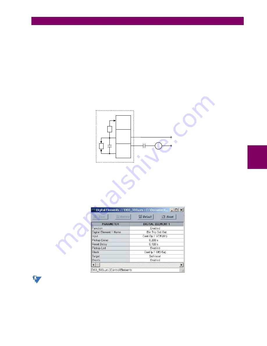
breaker is closed. The settings to use digital element 1 to monitor the breaker trip circuit are indicated below (EnerVista UR
Setup example shown):
The PICKUP DELAY setting should be greater than the operating time of the breaker to avoid nuisance alarms.
7ULSFRLO
D
85VHULHVGHYLFH
ZLWKIRUP$FRQWDFWV
, FXUUHQWPRQLWRU
9 YROWDJHPRQLWRU
'&²
$&'5
+D
+E
+F
,
9
'&
NOTE
Содержание L30
Страница 10: ...x L30 Line Current Differential System GE Multilin TABLE OF CONTENTS ...
Страница 30: ...1 20 L30 Line Current Differential System GE Multilin 1 5 USING THE RELAY 1 GETTING STARTED 1 ...
Страница 58: ...2 28 L30 Line Current Differential System GE Multilin 2 4 SPECIFICATIONS 2 PRODUCT DESCRIPTION 2 ...
Страница 126: ...4 30 L30 Line Current Differential System GE Multilin 4 3 FACEPLATE INTERFACE 4 HUMAN INTERFACES 4 ...
Страница 370: ...5 244 L30 Line Current Differential System GE Multilin 5 10 TESTING 5 SETTINGS 5 ...
Страница 396: ...6 26 L30 Line Current Differential System GE Multilin 6 5 PRODUCT INFORMATION 6 ACTUAL VALUES 6 ...
Страница 450: ...10 10 L30 Line Current Differential System GE Multilin 10 4 INSTANTANEOUS ELEMENTS 10 APPLICATION OF SETTINGS 10 ...
Страница 464: ...A 10 L30 Line Current Differential System GE Multilin A 1 PARAMETER LISTS APPENDIX A A ...
Страница 600: ...C 30 L30 Line Current Differential System GE Multilin C 7 LOGICAL NODES APPENDIX C C ...
Страница 610: ...D 10 L30 Line Current Differential System GE Multilin D 1 IEC 60870 5 104 APPENDIX D D ...
Страница 622: ...E 12 L30 Line Current Differential System GE Multilin E 2 DNP POINT LISTS APPENDIX E E ...
Страница 634: ...F 12 L30 Line Current Differential System GE Multilin F 3 WARRANTY APPENDIX F F ...
Страница 644: ...x L30 Line Current Differential System GE Multilin INDEX ...