


GE Multilin
L30 Line Current Differential System
5-73
5 SETTINGS
5.4 SYSTEM SETUP
5
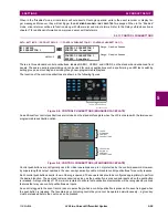
The
FREQUENCY AND PHASE REFERENCE
setting determines which signal source is used (and hence which AC signal) for
phase angle reference. The AC signal used is prioritized based on the AC inputs that are configured for the signal source:
phase voltages takes precedence, followed by auxiliary voltage, then phase currents, and finally ground current.
For three phase selection, phase A is used for angle referencing (
), while Clarke transformation of the
phase signals is used for frequency metering and tracking (
) for better performance dur-
ing fault, open pole, and VT and CT fail conditions.
The phase reference and frequency tracking AC signals are selected based upon the Source configuration, regardless of
whether or not a particular signal is actually applied to the relay.
Phase angle of the reference signal will always display zero degrees and all other phase angles will be relative to this sig-
nal. If the pre-selected reference signal is not measurable at a given time, the phase angles are not referenced.
The phase angle referencing is done via a phase locked loop, which can synchronize independent UR-series relays if they
have the same AC signal reference. This results in very precise correlation of phase angle indications between different
UR-series relays.
FREQUENCY TRACKING
is set to
“
Disabled
”
only in unusual circumstances; consult the factory for special variable-
frequency applications.
The frequency tracking feature functions only when the L30 is in the “Programmed” mode. If the L30 is “Not Pro-
grammed”, then metering values are available but can exhibit significant errors.
The nominal system frequency should be selected as 50 Hz or 60 Hz only. The
FREQUENCY AND PHASE REFERENCE
setting, used as a reference for calculating all angles, must be identical for all terminals. Whenever the 87L function
is “Enabled”, the frequency tracking function is disabled, and frequency tracking is driven by the L30 algorithm (see
the
Theory of operation
chapter). Whenever the 87L function is “Disabled”, the frequency tracking mechanism
reverts to the UR-series mechanism which uses the
FREQUENCY TRACKING
setting to provide frequency tracking for
all other elements and functions.
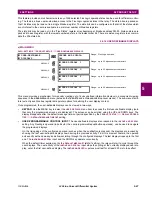
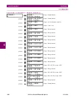
5.4.3 SIGNAL SOURCES
PATH: SETTINGS
SYSTEM SETUP
SIGNAL SOURCES
SOURCE 1(4)
Identical menus are available for each source. The "SRC 1" text can be replaced by with a user-defined name appropriate
for the associated source.
The first letter in the source identifier represents the module slot position. The number directly following this letter repre-
sents either the first bank of four channels (1, 2, 3, 4) called “1” or the second bank of four channels (5, 6, 7, 8) called “5” in
a particular CT/VT module. Refer to the
Introduction to AC sources
section at the beginning of this chapter for additional
details on this concept.
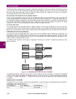
It is possible to select the sum of all CT combinations. The first channel displayed is the CT to which all others will be
referred. For example, the selection “F1+F5” indicates the sum of each phase from channels “F1” and “F5”, scaled to
whichever CT has the higher ratio. Selecting “None” hides the associated actual values.
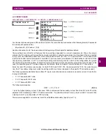
SOURCE 1
SOURCE 1 NAME:
SRC 1
Range: up to six alphanumeric characters
MESSAGE
SOURCE 1 PHASE CT:
None
Range: None, F1, F5, F1+F5,... up to a combination of
any 6 CTs. Only Phase CT inputs are displayed.
MESSAGE
SOURCE 1 GROUND CT:
None
Range: None, F1, F5, F1+F5,... up to a combination of
any 6 CTs. Only Ground CT inputs are displayed.
MESSAGE
SOURCE 1 PHASE VT:
None
Range: None, F5, L5
Only phase voltage inputs will be displayed.
MESSAGE
SOURCE 1 AUX VT:
None
Range: None, F5, L5
Only auxiliary voltage inputs will be displayed.
V
ANGLE REF
V
A
=
V
FREQUENCY
2
V
A
V
B
–
V
C
–
3
=
NOTE
NOTE
NOTE
Содержание L30
Страница 10: ...x L30 Line Current Differential System GE Multilin TABLE OF CONTENTS ...
Страница 30: ...1 20 L30 Line Current Differential System GE Multilin 1 5 USING THE RELAY 1 GETTING STARTED 1 ...
Страница 58: ...2 28 L30 Line Current Differential System GE Multilin 2 4 SPECIFICATIONS 2 PRODUCT DESCRIPTION 2 ...
Страница 126: ...4 30 L30 Line Current Differential System GE Multilin 4 3 FACEPLATE INTERFACE 4 HUMAN INTERFACES 4 ...
Страница 370: ...5 244 L30 Line Current Differential System GE Multilin 5 10 TESTING 5 SETTINGS 5 ...
Страница 396: ...6 26 L30 Line Current Differential System GE Multilin 6 5 PRODUCT INFORMATION 6 ACTUAL VALUES 6 ...
Страница 450: ...10 10 L30 Line Current Differential System GE Multilin 10 4 INSTANTANEOUS ELEMENTS 10 APPLICATION OF SETTINGS 10 ...
Страница 464: ...A 10 L30 Line Current Differential System GE Multilin A 1 PARAMETER LISTS APPENDIX A A ...
Страница 600: ...C 30 L30 Line Current Differential System GE Multilin C 7 LOGICAL NODES APPENDIX C C ...
Страница 610: ...D 10 L30 Line Current Differential System GE Multilin D 1 IEC 60870 5 104 APPENDIX D D ...
Страница 622: ...E 12 L30 Line Current Differential System GE Multilin E 2 DNP POINT LISTS APPENDIX E E ...
Страница 634: ...F 12 L30 Line Current Differential System GE Multilin F 3 WARRANTY APPENDIX F F ...
Страница 644: ...x L30 Line Current Differential System GE Multilin INDEX ...