


GE Multilin
L30 Line Current Differential System
5-195
5 SETTINGS
5.7 CONTROL ELEMENTS
5
If one or both sources are de-energized, the synchrocheck programming can allow for closing of the circuit breaker using
undervoltage control to by-pass the synchrocheck measurements (dead source function).
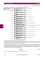
•
SYNCHK1 V1 SOURCE
: This setting selects the source for voltage V1 (see NOTES below).
•
SYNCHK1 V2 SOURCE
: This setting selects the source for voltage V2, which must not be the same as used for the
V1 (see NOTES below).
•
SYNCHK1 MAX VOLT DIFF
: This setting selects the maximum primary voltage difference in volts between the two
sources. A primary voltage magnitude difference between the two input voltages below this value is within the permis-
sible limit for synchronism.
•
SYNCHK1 MAX ANGLE DIFF:
This setting selects the maximum angular difference in degrees between the two
sources. An angular difference between the two input voltage phasors below this value is within the permissible limit
for synchronism.
•
SYNCHK1 MAX FREQ DIFF:
This setting selects the maximum frequency difference in ‘Hz’ between the two sources.
A frequency difference between the two input voltage systems below this value is within the permissible limit for syn-
chronism.
•
SYNCHK1 MAX FREQ HYSTERESIS
: This setting specifies the required hysteresis for the maximum frequency differ-
ence condition. The condition becomes satisfied when the frequency difference becomes lower than
SYNCHK1 MAX
FREQ DIFF
. Once the Synchrocheck element has operated, the frequency difference must increase above the
SYNCHK1
MAX FREQ DIFF
+
SYNCHK1 MAX FREQ HYSTERESIS
sum to drop out (assuming the other two conditions, voltage and
angle, remain satisfied).
•
SYNCHK1 DEAD SOURCE SELECT:
This setting selects the combination of dead and live sources that will by-pass
synchronism check function and permit the breaker to be closed when one or both of the two voltages (V1 or/and V2)
are below the maximum voltage threshold. A dead or live source is declared by monitoring the voltage level. Six
options are available:
None:
Dead Source function is disabled
LV1 and DV2:
Live V1 and Dead V2
DV1 and LV2:
Dead V1 and Live V2
DV1 or DV2:
Dead V1 or Dead V2
DV1 Xor DV2:
Dead V1 exclusive-or Dead V2 (one source is Dead and the other is Live)
DV1 and DV2:
Dead V1 and Dead V2
•
SYNCHK1 DEAD V1 MAX VOLT:
This setting establishes a maximum voltage magnitude for V1 in 1 ‘pu’. Below this
magnitude, the V1 voltage input used for synchrocheck will be considered “Dead” or de-energized.
•
SYNCHK1 DEAD V2 MAX VOLT
: This setting establishes a maximum voltage magnitude for V2 in ‘pu’. Below this
magnitude, the V2 voltage input used for synchrocheck will be considered “Dead” or de-energized.
•
SYNCHK1 LIVE V1 MIN VOLT
: This setting establishes a minimum voltage magnitude for V1 in ‘pu’. Above this mag-
nitude, the V1 voltage input used for synchrocheck will be considered “Live” or energized.
•
SYNCHK1 LIVE V2 MIN VOLT
: This setting establishes a minimum voltage magnitude for V2 in ‘pu’. Above this mag-
nitude, the V2 voltage input used for synchrocheck will be considered “Live” or energized.
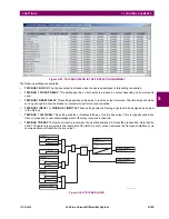
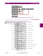
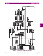
NOTES ON THE SYNCHROCHECK FUNCTION:
1.
The selected sources for synchrocheck inputs V1 and V2 (which must not be the same source) may include both a
three-phase and an auxiliary voltage. The relay will automatically select the specific voltages to be used by the syn-
chrocheck element in accordance with the following table.
NO.
V1 OR V2
(SOURCE Y)
V2 OR V1
(SOURCE Z)
AUTO-SELECTED
COMBINATION
AUTO-SELECTED VOLTAGE
SOURCE Y
SOURCE Z
1
Phase VTs and
Auxiliary VT
Phase VTs and
Auxiliary VT
Phase
Phase
VAB
2
Phase VTs and
Auxiliary VT
Phase VT
Phase
Phase
VAB
3
Phase VT
Phase VT
Phase
Phase
VAB
Содержание L30
Страница 10: ...x L30 Line Current Differential System GE Multilin TABLE OF CONTENTS ...
Страница 30: ...1 20 L30 Line Current Differential System GE Multilin 1 5 USING THE RELAY 1 GETTING STARTED 1 ...
Страница 58: ...2 28 L30 Line Current Differential System GE Multilin 2 4 SPECIFICATIONS 2 PRODUCT DESCRIPTION 2 ...
Страница 126: ...4 30 L30 Line Current Differential System GE Multilin 4 3 FACEPLATE INTERFACE 4 HUMAN INTERFACES 4 ...
Страница 370: ...5 244 L30 Line Current Differential System GE Multilin 5 10 TESTING 5 SETTINGS 5 ...
Страница 396: ...6 26 L30 Line Current Differential System GE Multilin 6 5 PRODUCT INFORMATION 6 ACTUAL VALUES 6 ...
Страница 450: ...10 10 L30 Line Current Differential System GE Multilin 10 4 INSTANTANEOUS ELEMENTS 10 APPLICATION OF SETTINGS 10 ...
Страница 464: ...A 10 L30 Line Current Differential System GE Multilin A 1 PARAMETER LISTS APPENDIX A A ...
Страница 600: ...C 30 L30 Line Current Differential System GE Multilin C 7 LOGICAL NODES APPENDIX C C ...
Страница 610: ...D 10 L30 Line Current Differential System GE Multilin D 1 IEC 60870 5 104 APPENDIX D D ...
Страница 622: ...E 12 L30 Line Current Differential System GE Multilin E 2 DNP POINT LISTS APPENDIX E E ...
Страница 634: ...F 12 L30 Line Current Differential System GE Multilin F 3 WARRANTY APPENDIX F F ...
Страница 644: ...x L30 Line Current Differential System GE Multilin INDEX ...