


5-196
L30 Line Current Differential System
GE Multilin
5.7 CONTROL ELEMENTS
5 SETTINGS
5
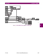
The voltages V1 and V2 will be matched automatically so that the corresponding voltages from the two sources will be
used to measure conditions. A phase to phase voltage will be used if available in both sources; if one or both of the
Sources have only an auxiliary voltage, this voltage will be used. For example, if an auxiliary voltage is programmed to
VAG, the synchrocheck element will automatically select VAG from the other source. If the comparison is required on a
specific voltage, the user can externally connect that specific voltage to auxiliary voltage terminals and then use this
"Auxiliary Voltage" to check the synchronism conditions.
If using a single CT/VT module with both phase voltages and an auxiliary voltage, ensure that only the auxiliary voltage
is programmed in one of the sources to be used for synchrocheck.
Exception:
Synchronism cannot be checked between Delta connected phase VTs and a Wye con-
nected auxiliary voltage.
2.
The relay measures frequency and Volts/Hz from an input on a given source with priorities as established by the con-
figuration of input channels to the source. The relay will use the phase channel of a three-phase set of voltages if pro-
grammed as part of that source. The relay will use the auxiliary voltage channel only if that channel is programmed as
part of the Source and a three-phase set is not.
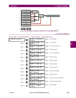
4
Phase VT and
Auxiliary VT
Auxiliary VT
Phase
Auxiliary
V auxiliary
(as set for Source z)
5
Auxiliary VT
Auxiliary VT
Auxiliary
Auxiliary
V auxiliary
(as set for selected sources)
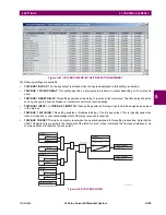
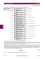
NO.
V1 OR V2
(SOURCE Y)
V2 OR V1
(SOURCE Z)
AUTO-SELECTED
COMBINATION
AUTO-SELECTED VOLTAGE
SOURCE Y
SOURCE Z
NOTE
Содержание L30
Страница 10: ...x L30 Line Current Differential System GE Multilin TABLE OF CONTENTS ...
Страница 30: ...1 20 L30 Line Current Differential System GE Multilin 1 5 USING THE RELAY 1 GETTING STARTED 1 ...
Страница 58: ...2 28 L30 Line Current Differential System GE Multilin 2 4 SPECIFICATIONS 2 PRODUCT DESCRIPTION 2 ...
Страница 126: ...4 30 L30 Line Current Differential System GE Multilin 4 3 FACEPLATE INTERFACE 4 HUMAN INTERFACES 4 ...
Страница 370: ...5 244 L30 Line Current Differential System GE Multilin 5 10 TESTING 5 SETTINGS 5 ...
Страница 396: ...6 26 L30 Line Current Differential System GE Multilin 6 5 PRODUCT INFORMATION 6 ACTUAL VALUES 6 ...
Страница 450: ...10 10 L30 Line Current Differential System GE Multilin 10 4 INSTANTANEOUS ELEMENTS 10 APPLICATION OF SETTINGS 10 ...
Страница 464: ...A 10 L30 Line Current Differential System GE Multilin A 1 PARAMETER LISTS APPENDIX A A ...
Страница 600: ...C 30 L30 Line Current Differential System GE Multilin C 7 LOGICAL NODES APPENDIX C C ...
Страница 610: ...D 10 L30 Line Current Differential System GE Multilin D 1 IEC 60870 5 104 APPENDIX D D ...
Страница 622: ...E 12 L30 Line Current Differential System GE Multilin E 2 DNP POINT LISTS APPENDIX E E ...
Страница 634: ...F 12 L30 Line Current Differential System GE Multilin F 3 WARRANTY APPENDIX F F ...
Страница 644: ...x L30 Line Current Differential System GE Multilin INDEX ...