


5-184
L30 Line Current Differential System
GE Multilin
5.7 CONTROL ELEMENTS
5 SETTINGS
5
5.7CONTROL ELEMENTS
5.7.1 OVERVIEW
Control elements are generally used for control rather than protection. See the
Introduction to Elements
section at the
beginning of this chapter for further information.
5.7.2 TRIP BUS
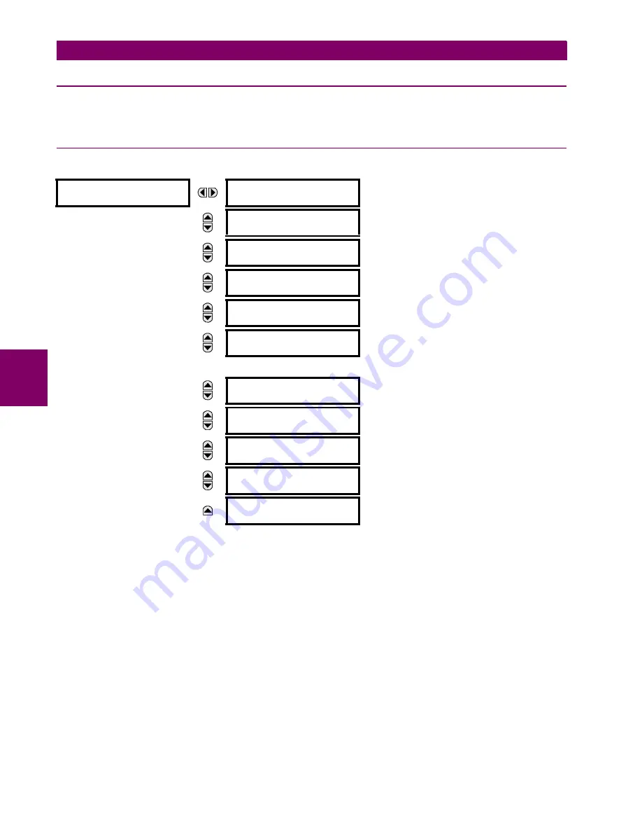
PATH: SETTINGS
CONTROL ELEMENTS
TRIP BUS
TRIP BUS 1(6)
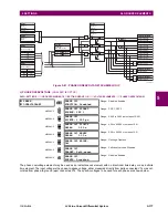
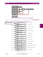
The trip bus element allows aggregating outputs of protection and control elements without using FlexLogic and assigning
them a simple and effective manner. Each trip bus can be assigned for either trip or alarm actions. Simple trip conditioning
such as latch, delay, and seal-in delay are available.
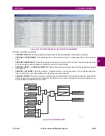
The easiest way to assign element outputs to a trip bus is through the EnerVista UR Setup software A protection summary
is displayed by navigating to a specific protection or control protection element and checking the desired bus box. Once the
desired element is selected for a specific bus, a list of element operate-type operands are displayed and can be assigned
to a trip bus. If more than one operate-type operand is required, it may be assigned directly from the trip bus menu.
TRIP BUS 1
TRIP BUS 1
FUNCTION: Disabled
Range: Enabled, Disabled
MESSAGE
TRIP BUS 1 BLOCK:
Off
Range: FlexLogic operand
MESSAGE
TRIP BUS 1 PICKUP
DELAY: 0.00
s
Range: 0.00 to 600.00 s in steps of 0.01
MESSAGE
TRIP BUS 1 RESET
DELAY: 0.00
s
Range: 0.00 to 600.00 s in steps of 0.01
MESSAGE
TRIP BUS 1 INPUT 1:
Off
Range: FlexLogic operand
MESSAGE
TRIP BUS 1 INPUT 2:
Off
Range: FlexLogic operand
MESSAGE
TRIP BUS 1 INPUT 16:
Off
Range: FlexLogic operand
MESSAGE
TRIP BUS 1
LATCHING: Disabled
Range: Enabled, Disabled
MESSAGE
TRIP BUS 1 RESET:
Off
Range: FlexLogic operand
MESSAGE
TRIP BUS 1 TARGET:
Self-reset
Range: Self-reset, Latched, Disabled
MESSAGE
TRIP BUS 1
EVENTS: Disabled
Range: Enabled, Disabled
Содержание L30
Страница 10: ...x L30 Line Current Differential System GE Multilin TABLE OF CONTENTS ...
Страница 30: ...1 20 L30 Line Current Differential System GE Multilin 1 5 USING THE RELAY 1 GETTING STARTED 1 ...
Страница 58: ...2 28 L30 Line Current Differential System GE Multilin 2 4 SPECIFICATIONS 2 PRODUCT DESCRIPTION 2 ...
Страница 126: ...4 30 L30 Line Current Differential System GE Multilin 4 3 FACEPLATE INTERFACE 4 HUMAN INTERFACES 4 ...
Страница 370: ...5 244 L30 Line Current Differential System GE Multilin 5 10 TESTING 5 SETTINGS 5 ...
Страница 396: ...6 26 L30 Line Current Differential System GE Multilin 6 5 PRODUCT INFORMATION 6 ACTUAL VALUES 6 ...
Страница 450: ...10 10 L30 Line Current Differential System GE Multilin 10 4 INSTANTANEOUS ELEMENTS 10 APPLICATION OF SETTINGS 10 ...
Страница 464: ...A 10 L30 Line Current Differential System GE Multilin A 1 PARAMETER LISTS APPENDIX A A ...
Страница 600: ...C 30 L30 Line Current Differential System GE Multilin C 7 LOGICAL NODES APPENDIX C C ...
Страница 610: ...D 10 L30 Line Current Differential System GE Multilin D 1 IEC 60870 5 104 APPENDIX D D ...
Страница 622: ...E 12 L30 Line Current Differential System GE Multilin E 2 DNP POINT LISTS APPENDIX E E ...
Страница 634: ...F 12 L30 Line Current Differential System GE Multilin F 3 WARRANTY APPENDIX F F ...
Страница 644: ...x L30 Line Current Differential System GE Multilin INDEX ...