


GE Multilin
L30 Line Current Differential System
1-7
1 GETTING STARTED
1.3 ENERVISTA UR SETUP SOFTWARE
1
•
To configure the L30 for remote access via the rear Ethernet port, see the
Configuring Ethernet Communications
sec-
tion. An Ethernet module must be specified at the time of ordering.
•
To configure the L30 for local access with a laptop through either the front RS232 port or rear Ethernet port, see the
Using the Quick Connect Feature
section.
b) CONFIGURING SERIAL COMMUNICATIONS
Before starting, verify that the serial cable is properly connected to the RS485 terminal on the back of the device. The face-
plate RS232 port is intended for local use and is not described in this section; see the
Using the Quick Connect Feature
section.
A GE Multilin F485 converter (or compatible RS232-to-RS485 converter) is required. Refer to the F485 instruction manual
for details.
1.
Verify that the latest version of the EnerVista UR Setup software is installed (available from the GE EnerVista CD or
online from
http://www.gedigitalenergy.com/multilin
). See the
Software Installation
section if not already installed.
2.
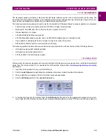
Select the “UR” device from the EnerVista Launchpad to start EnerVista UR Setup.
3.
Click the
Device Setup
button to open the Device Setup window and click the
Add Site
button to define a new site.
4.
Enter a site name in the “Site Name” field. Optionally add a short description of the site along with the display order of
devices defined for the site. In this example, we use “Location 1” as the site name. Click the
OK
button when complete.
The new site appears in the upper-left list in the EnerVista UR Setup window.
5.
Click the
Device Setup
button, then select the new site to re-open the Device Setup window.
6.
Click the
Add Device
button to define the new device.
7.
Enter a name in the "Device Name” field and a description (optional) of the site.
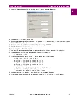
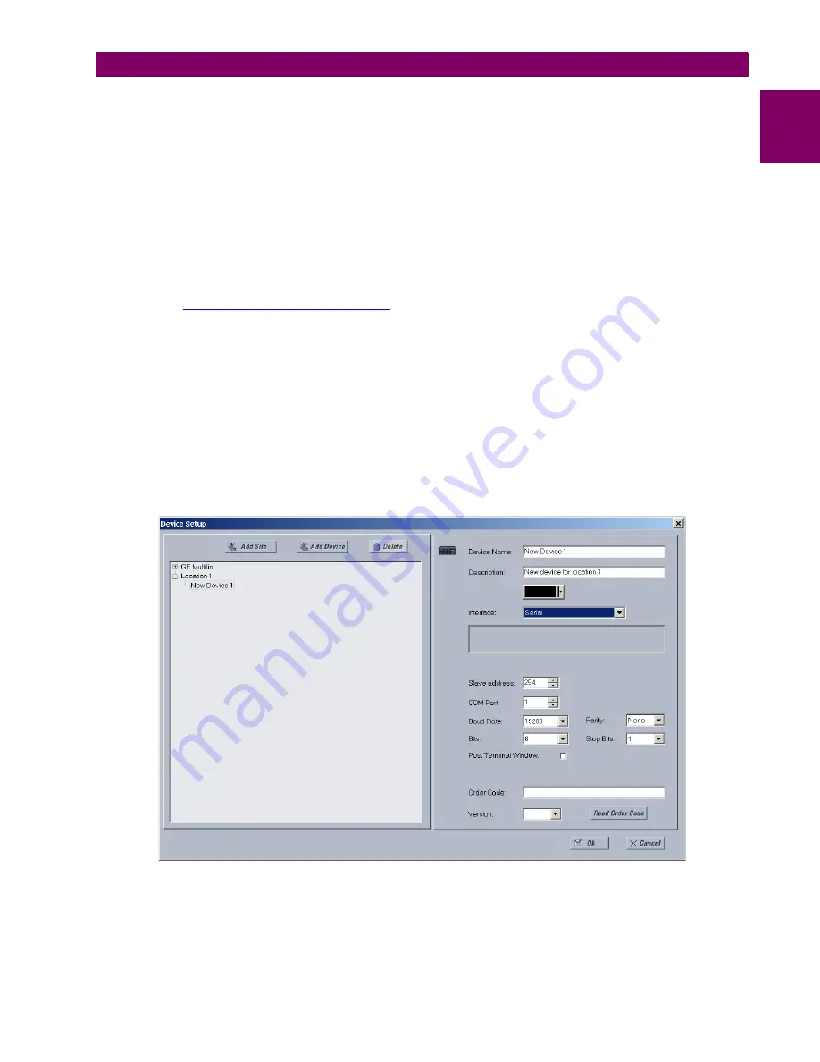
8.
Select “Serial” from the
Interface
drop-down list. This displays a number of interface parameters that must be entered
for serial communications.
Figure 1–4: CONFIGURING SERIAL COMMUNICATIONS
9.
Enter the relay slave address, COM port, baud rate, and parity settings from the
SETTINGS
PRODUCT SETUP
COM-
MUNICATIONS
SERIAL PORTS
menu in their respective fields.
Содержание L30
Страница 10: ...x L30 Line Current Differential System GE Multilin TABLE OF CONTENTS ...
Страница 30: ...1 20 L30 Line Current Differential System GE Multilin 1 5 USING THE RELAY 1 GETTING STARTED 1 ...
Страница 58: ...2 28 L30 Line Current Differential System GE Multilin 2 4 SPECIFICATIONS 2 PRODUCT DESCRIPTION 2 ...
Страница 126: ...4 30 L30 Line Current Differential System GE Multilin 4 3 FACEPLATE INTERFACE 4 HUMAN INTERFACES 4 ...
Страница 370: ...5 244 L30 Line Current Differential System GE Multilin 5 10 TESTING 5 SETTINGS 5 ...
Страница 396: ...6 26 L30 Line Current Differential System GE Multilin 6 5 PRODUCT INFORMATION 6 ACTUAL VALUES 6 ...
Страница 450: ...10 10 L30 Line Current Differential System GE Multilin 10 4 INSTANTANEOUS ELEMENTS 10 APPLICATION OF SETTINGS 10 ...
Страница 464: ...A 10 L30 Line Current Differential System GE Multilin A 1 PARAMETER LISTS APPENDIX A A ...
Страница 600: ...C 30 L30 Line Current Differential System GE Multilin C 7 LOGICAL NODES APPENDIX C C ...
Страница 610: ...D 10 L30 Line Current Differential System GE Multilin D 1 IEC 60870 5 104 APPENDIX D D ...
Страница 622: ...E 12 L30 Line Current Differential System GE Multilin E 2 DNP POINT LISTS APPENDIX E E ...
Страница 634: ...F 12 L30 Line Current Differential System GE Multilin F 3 WARRANTY APPENDIX F F ...
Страница 644: ...x L30 Line Current Differential System GE Multilin INDEX ...