


9-4
L30 Line Current Differential System
GE Multilin
9.1 OVERVIEW
9 THEORY OF OPERATION
9
(EQ 9.10)
The fault severity for each phase is determined by following equation:
(EQ 9.11)
where
P
is the pickup setting.
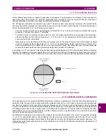
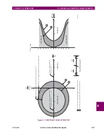
This equation is based on the adaptive strategy and yields an elliptical restraint characteristic. The elliptical area is the
restraint region. When the adaptive portion of the restraint current is small, the restraint region shrinks. When the adaptive
portion of the restraint current increases, the restraint region grows to reflect the uncertainty of the measurement. The com-
puted severity increases with the probability that the sum of the measured currents indicates a fault. With the exception of
“Restraint”, all quantities are defined in previous sections. “Adaptive Restraint” is a restraint multiplier, analogous to the
slope setting of traditional differential approaches, for adjusting the sensitivity of the relay.
Raising the restraint multiplier corresponds to demanding a greater confidence interval, and has the effect of decreasing
sensitivity while lowering it is equivalent to relaxing the confidence interval and increases sensitivity. Thus, the restraint
multiplier is an application adjustment that is used to achieve the desired balance between sensitivity and security. The
computed severity is zero when the operate phasor is on the elliptical boundary, is negative inside the boundary, and posi-
tive outside the boundary. Outside of the restraint boundary, the computed severity grows as the square of the fault current.
The restraint area grows as the square of the error in the measurements.
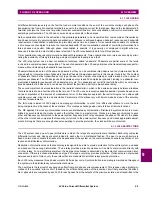
9.1.7 GROUND DIFFERENTIAL ELEMENT
The line ground differential function allows sensitive ground protection for single-line to-ground faults, allowing the phase
differential element to be set higher (above load) to provide protection for multi-phase faults. The L30 ground differential
function calculates ground differential current from all terminal phase currents. The maximum phase current is used for the
restraint. The L30 is applied in dual-breaker applications to cope with significant through current at remote terminals that
may cause CT errors or saturation.
The line ground differential function uses the same CT matched and time-aligned phasors as the phase-segregated current
differential function. The operate signal is calculated for both real and imaginary parts as follows:
(EQ 9.12)
(EQ 9.13)
The terms for the second remote terminal are omitted in two-terminal applications.
The maximum through current is available locally and re-constructed from the received remote restraint based on the max-
imum remote restraint current shown in the previous section and as indicated below.
For two-terminal applications:
(EQ 9.14)
For three-terminal applications:
I
REST_A
2
I
LOC_PHASOR_RESTRAINT_A
2
I
REM1_PHASOR_RESTRAINT_A
2
I
REM2_PHASOR_RESTRAINT_A
2
+
+
=
S
A
I
DIFF_A
2
2
P
2
I
REST_A
2
+
–
=
I
OP_87G_RE
I
LOC_PHASOR_RE_A
I
LOC_PHASOR_RE_B
I
LOC_PHASOR_RE_C
I
REM1_PHASOR_RE_A
I
REM1_PHASOR_RE_B
+
+
+
+
=
I
REM1_PHASOR_RE_C
I
REM2_PHASOR_RE_A
I
REM2_PHASOR_RE_B
I
REM2_PHASOR_RE_C
+
+
+
+
I
OP_87G_IM
I
LOC_PHASOR_IM_A
I
LOC_PHASOR_IM_B
I
LOC_PHASOR_IM_C
I
REM1_PHASOR_IM_A
I
REM1_PHASOR_IM_B
+
+
+
+
=
I
REM1_PHASOR_IM_C
I
REM2_PHASOR_IM_A
I
REM2_PHASOR_IM_B
I
REM2_PHASOR_IM_C
+
+
+
+
If
I
REM_REST_A
2
BP
2
, then
I
REM_REST_A
2
I
REM_RESTRAINT_A
2
2
S
1
2
-----------------------------------------------------
=
else
I
REM_REST_A
2
I
REM_RESTRAINT_A
2
2
S
1
BP
2
–
2
S
2
2
-------------------------------------------------------------------------------------------
BP
2
+
=
Содержание L30
Страница 10: ...x L30 Line Current Differential System GE Multilin TABLE OF CONTENTS ...
Страница 30: ...1 20 L30 Line Current Differential System GE Multilin 1 5 USING THE RELAY 1 GETTING STARTED 1 ...
Страница 58: ...2 28 L30 Line Current Differential System GE Multilin 2 4 SPECIFICATIONS 2 PRODUCT DESCRIPTION 2 ...
Страница 126: ...4 30 L30 Line Current Differential System GE Multilin 4 3 FACEPLATE INTERFACE 4 HUMAN INTERFACES 4 ...
Страница 370: ...5 244 L30 Line Current Differential System GE Multilin 5 10 TESTING 5 SETTINGS 5 ...
Страница 396: ...6 26 L30 Line Current Differential System GE Multilin 6 5 PRODUCT INFORMATION 6 ACTUAL VALUES 6 ...
Страница 450: ...10 10 L30 Line Current Differential System GE Multilin 10 4 INSTANTANEOUS ELEMENTS 10 APPLICATION OF SETTINGS 10 ...
Страница 464: ...A 10 L30 Line Current Differential System GE Multilin A 1 PARAMETER LISTS APPENDIX A A ...
Страница 600: ...C 30 L30 Line Current Differential System GE Multilin C 7 LOGICAL NODES APPENDIX C C ...
Страница 610: ...D 10 L30 Line Current Differential System GE Multilin D 1 IEC 60870 5 104 APPENDIX D D ...
Страница 622: ...E 12 L30 Line Current Differential System GE Multilin E 2 DNP POINT LISTS APPENDIX E E ...
Страница 634: ...F 12 L30 Line Current Differential System GE Multilin F 3 WARRANTY APPENDIX F F ...
Страница 644: ...x L30 Line Current Differential System GE Multilin INDEX ...