


GE Multilin
L30 Line Current Differential System
5-153
5 SETTINGS
5.6 GROUPED ELEMENTS
5
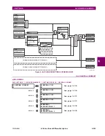
e) PHASE DIRECTIONAL OVERCURRENT
(ANSI 67P, IEC PDOC/PTOC)
PATH: SETTINGS
GROUPED ELEMENTS
SETTING GROUP 1(6)
PHASE CURRENT
PHASE DIRECTIONAL 1(2)
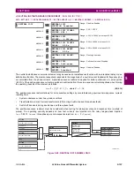
The phase directional elements (one for each of phases A, B, and C) determine the phase current flow direction for steady
state and fault conditions and can be used to control the operation of the phase overcurrent elements via the
BLOCK
inputs
of these elements.
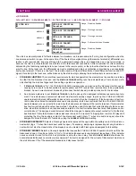
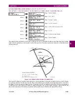
Figure 5–65: PHASE A DIRECTIONAL POLARIZATION
This element is intended to apply a block signal to an overcurrent element to prevent an operation when current is flowing
in a particular direction. The direction of current flow is determined by measuring the phase angle between the current from
the phase CTs and the line-line voltage from the VTs, based on the 90° or quadrature connection. If there is a requirement
to supervise overcurrent elements for flows in opposite directions, such as can happen through a bus-tie breaker, two
phase directional elements should be programmed with opposite element characteristic angle (ECA) settings.
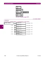
PHASE
DIRECTIONAL 1
PHASE DIR 1
FUNCTION: Disabled
Range: Disabled, Enabled
MESSAGE
PHASE DIR 1 SIGNAL
SOURCE: SRC 1
Range: SRC 1, SRC 2
MESSAGE
PHASE DIR 1 BLOCK:
Off
Range: FlexLogic™ operand
MESSAGE
PHASE DIR 1
ECA: 30
Range: 0 to 359° in steps of 1
MESSAGE
PHASE DIR POL V1
THRESHOLD: 0.700 pu
Range: 0.000 to 3.000 pu in steps of 0.001
MESSAGE
PHASE DIR 1 BLOCK
WHEN V MEM EXP: No
Range: No, Yes
MESSAGE
PHASE DIR 1
TARGET: Self-reset
Range: Self-reset, Latched, Disabled
MESSAGE
PHASE DIR 1
EVENTS: Disabled
Range: Disabled, Enabled
827800A2.CDR
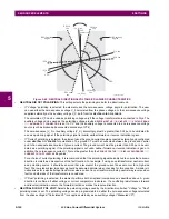
VBG
VCG
VAG(Faulted)
IA
ECA
set at 30°
ECA = Element Characteristic Angle at 30°
IA = operating current
Phasors for Phase A Polarization:
VPol = VBC
(1/_ECA) = polarizing voltage
×
Fault angle
set at 60° Lag
VAG (Unfaulted)
OUTPUT
S
0
1
VBC
VBC
VPol
+90°
–90°
Содержание L30
Страница 10: ...x L30 Line Current Differential System GE Multilin TABLE OF CONTENTS ...
Страница 30: ...1 20 L30 Line Current Differential System GE Multilin 1 5 USING THE RELAY 1 GETTING STARTED 1 ...
Страница 58: ...2 28 L30 Line Current Differential System GE Multilin 2 4 SPECIFICATIONS 2 PRODUCT DESCRIPTION 2 ...
Страница 126: ...4 30 L30 Line Current Differential System GE Multilin 4 3 FACEPLATE INTERFACE 4 HUMAN INTERFACES 4 ...
Страница 370: ...5 244 L30 Line Current Differential System GE Multilin 5 10 TESTING 5 SETTINGS 5 ...
Страница 396: ...6 26 L30 Line Current Differential System GE Multilin 6 5 PRODUCT INFORMATION 6 ACTUAL VALUES 6 ...
Страница 450: ...10 10 L30 Line Current Differential System GE Multilin 10 4 INSTANTANEOUS ELEMENTS 10 APPLICATION OF SETTINGS 10 ...
Страница 464: ...A 10 L30 Line Current Differential System GE Multilin A 1 PARAMETER LISTS APPENDIX A A ...
Страница 600: ...C 30 L30 Line Current Differential System GE Multilin C 7 LOGICAL NODES APPENDIX C C ...
Страница 610: ...D 10 L30 Line Current Differential System GE Multilin D 1 IEC 60870 5 104 APPENDIX D D ...
Страница 622: ...E 12 L30 Line Current Differential System GE Multilin E 2 DNP POINT LISTS APPENDIX E E ...
Страница 634: ...F 12 L30 Line Current Differential System GE Multilin F 3 WARRANTY APPENDIX F F ...
Страница 644: ...x L30 Line Current Differential System GE Multilin INDEX ...