


GE Multilin
L30 Line Current Differential System
10-3
10 APPLICATION OF SETTINGS
10.2 CURRENT DIFFERENTIAL (87L) SETTINGS
10
10.2CURRENT DIFFERENTIAL (87L) SETTINGS
10.2.1 INTRODUCTION
Software is available from the GE Multilin website that is helpful in selecting settings for the specific appli-
cation. Checking the performance of selected element settings with respect to known power system fault
parameters makes it relatively simple to choose the optimum settings for the application.
This software program is also very useful for establishing test parameters. It is strongly recommended this
program be downloaded.
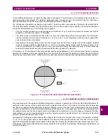
The differential characteristic is defined by four settings:
CURRENT DIFF PICKUP
,
CURRENT DIFF RESTRAINT 1
,
CURRENT DIFF
RESTRAINT 2
, and
CURRENT DIFF BREAK PT
(breakpoint). As is typical for current-based differential elements, the settings
are a trade-off between operation on internal faults against restraint during external faults.
10.2.2 CURRENT DIFFERENTIAL PICKUP
This setting established the sensitivity of the element to high impedance faults, and it is therefore desirable to choose a low
level, but this can cause a maloperation for an external fault causing CT saturation. The selection of this setting is influ-
enced by the decision to use charging current compensation. If charging current compensation is Enabled, pickup should
be set to a minimum of 150% of the steady-state line charging current, to a lower limit of 10% of CT rating. If charging cur-
rent compensation is Disabled, pickup should be set to a minimum of 250% of the steady-state line charging current to a
lower limit of 10% of CT rating.
If the CT at one terminal can saturate while the CTs at other terminals do not, this setting should be increased by approxi-
mately 20 to 50% (depending on how heavily saturated the one CT is while the other CTs are not saturated) of CT rating to
prevent operation on a close-in external fault.
10.2.3 CURRENT DIFF RESTRAINT 1
This setting controls the element characteristic when current is below the breakpoint, where CT errors and saturation
effects are not expected to be significant. The setting is used to provide sensitivity to high impedance internal faults, or
when system configuration limits the fault current to low values. A setting of 10 to 20% is appropriate in most cases, but this
should be raised to 30% if the CTs can perform quite differently during faults.
10.2.4 CURRENT DIFF RESTRAINT 2
This setting controls the element characteristic when current is above the breakpoint, where CT errors and saturation
effects are expected to be significant. The setting is used to provide security against high current external faults. A setting
of 30 to 40% is appropriate in most cases, but this should be raised to 70% if the CTs can perform quite differently during
faults.
Assigning the
CURRENT DIFF RESTRAINT 1(2)
settings to the same value reverts dual slope bias characteristics into
single slope bias characteristics.
10.2.5 CURRENT DIFF BREAK POINT
This setting controls the threshold where the relay changes from using the restraint 1 to the restraint 2 characteristics. Two
approaches can be considered.
1.
Program the setting to 150 to 200% of the maximum emergency load current on the line, on the assumption that a
maintained current above this level is a fault.
2.
Program the setting below the current level where CT saturation and spurious transient differential currents can be
expected.
The first approach gives comparatively more security and less sensitivity; the second approach provides less security for
more sensitivity.
NOTE
NOTE
Содержание L30
Страница 10: ...x L30 Line Current Differential System GE Multilin TABLE OF CONTENTS ...
Страница 30: ...1 20 L30 Line Current Differential System GE Multilin 1 5 USING THE RELAY 1 GETTING STARTED 1 ...
Страница 58: ...2 28 L30 Line Current Differential System GE Multilin 2 4 SPECIFICATIONS 2 PRODUCT DESCRIPTION 2 ...
Страница 126: ...4 30 L30 Line Current Differential System GE Multilin 4 3 FACEPLATE INTERFACE 4 HUMAN INTERFACES 4 ...
Страница 370: ...5 244 L30 Line Current Differential System GE Multilin 5 10 TESTING 5 SETTINGS 5 ...
Страница 396: ...6 26 L30 Line Current Differential System GE Multilin 6 5 PRODUCT INFORMATION 6 ACTUAL VALUES 6 ...
Страница 450: ...10 10 L30 Line Current Differential System GE Multilin 10 4 INSTANTANEOUS ELEMENTS 10 APPLICATION OF SETTINGS 10 ...
Страница 464: ...A 10 L30 Line Current Differential System GE Multilin A 1 PARAMETER LISTS APPENDIX A A ...
Страница 600: ...C 30 L30 Line Current Differential System GE Multilin C 7 LOGICAL NODES APPENDIX C C ...
Страница 610: ...D 10 L30 Line Current Differential System GE Multilin D 1 IEC 60870 5 104 APPENDIX D D ...
Страница 622: ...E 12 L30 Line Current Differential System GE Multilin E 2 DNP POINT LISTS APPENDIX E E ...
Страница 634: ...F 12 L30 Line Current Differential System GE Multilin F 3 WARRANTY APPENDIX F F ...
Страница 644: ...x L30 Line Current Differential System GE Multilin INDEX ...