


GE Multilin
L30 Line Current Differential System
5-185
5 SETTINGS
5.7 CONTROL ELEMENTS
5
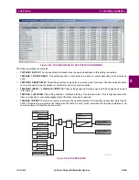
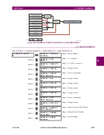
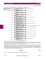
Figure 5–87: TRIP BUS FIELDS IN THE PROTECTION SUMMARY
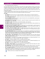
The following settings are available.
•
TRIP BUS 1 BLOCK
: The trip bus output is blocked when the operand assigned to this setting is asserted.
•
TRIP BUS 1 PICKUP DELAY
: This setting specifies a time delay to produce an output depending on how output is
used.
•
TRIP BUS 1 RESET DELAY
: This setting specifies a time delay to reset an output command. The time delay should be
set long enough to allow the breaker or contactor to perform a required action.
•
TRIP BUS 1 INPUT 1
to
TRIP BUS 1 INPUT 16
: These settings select a FlexLogic operand to be assigned as an input
to the trip bus.
•
TRIP BUS 1 LATCHING
: This setting enables or disables latching of the trip bus output. This is typically used when
lockout is required or user acknowledgement of the relay response is required.
•
TRIP BUS 1 RESET
: The trip bus output is reset when the operand assigned to this setting is asserted. Note that the
RESET OP
operand is pre-wired to the reset gate of the latch, As such, a reset command the front panel interface or via
communications will reset the trip bus output.
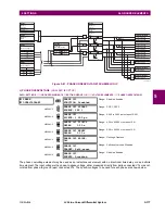
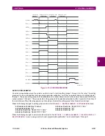
Figure 5–88: TRIP BUS LOGIC
***
SETTINGS
= Off
TRIP BUS 1 INPUT 2
= Off
TRIP BUS 1 INPUT 1
= Off
TRIP BUS 1 INPUT 16
OR
SETTINGS
= Enabled
TRIP BUS 1
FUNCTION
= Off
TRIP BUS 1 BLOCK
AND
AND
Latch
S
R
Non-volatile,
set-dominant
SETTINGS
= Enabled
TRIP BUS 1
LATCHING
= Off
TRIP BUS 1 RESET
FLEXLOGIC OPERAND
TRIP BUS 1 PKP
OR
SETTINGS
TRIP BUS 1 PICKUP
DELAY
TRIP BUS 1 RESET
DELAY
T
PKP
T
RST
FLEXLOGIC OPERAND
RESET OP
FLEXLOGIC OPERAND
TRIP BUS 1 OP
842023A1.CDR
Содержание L30
Страница 10: ...x L30 Line Current Differential System GE Multilin TABLE OF CONTENTS ...
Страница 30: ...1 20 L30 Line Current Differential System GE Multilin 1 5 USING THE RELAY 1 GETTING STARTED 1 ...
Страница 58: ...2 28 L30 Line Current Differential System GE Multilin 2 4 SPECIFICATIONS 2 PRODUCT DESCRIPTION 2 ...
Страница 126: ...4 30 L30 Line Current Differential System GE Multilin 4 3 FACEPLATE INTERFACE 4 HUMAN INTERFACES 4 ...
Страница 370: ...5 244 L30 Line Current Differential System GE Multilin 5 10 TESTING 5 SETTINGS 5 ...
Страница 396: ...6 26 L30 Line Current Differential System GE Multilin 6 5 PRODUCT INFORMATION 6 ACTUAL VALUES 6 ...
Страница 450: ...10 10 L30 Line Current Differential System GE Multilin 10 4 INSTANTANEOUS ELEMENTS 10 APPLICATION OF SETTINGS 10 ...
Страница 464: ...A 10 L30 Line Current Differential System GE Multilin A 1 PARAMETER LISTS APPENDIX A A ...
Страница 600: ...C 30 L30 Line Current Differential System GE Multilin C 7 LOGICAL NODES APPENDIX C C ...
Страница 610: ...D 10 L30 Line Current Differential System GE Multilin D 1 IEC 60870 5 104 APPENDIX D D ...
Страница 622: ...E 12 L30 Line Current Differential System GE Multilin E 2 DNP POINT LISTS APPENDIX E E ...
Страница 634: ...F 12 L30 Line Current Differential System GE Multilin F 3 WARRANTY APPENDIX F F ...
Страница 644: ...x L30 Line Current Differential System GE Multilin INDEX ...