


GE Multilin
L30 Line Current Differential System
2-5
2 PRODUCT DESCRIPTION
2.1 INTRODUCTION
2
MOUNT/COATING
H
|
|
|
|
|
|
|
|
|
Horizontal (19” rack)
A
|
|
|
|
|
|
|
|
|
Horizontal (19” rack) with harsh environmental coating
FACEPLATE/ DISPLAY
C
|
|
|
|
|
|
|
|
English display
D
|
|
|
|
|
|
|
|
French display
R
|
|
|
|
|
|
|
|
Russian display
A
|
|
|
|
|
|
|
|
Chinese display
P
|
|
|
|
|
|
|
|
English display with 4 small and 12 large programmable pushbuttons
G
|
|
|
|
|
|
|
|
French display with 4 small and 12 large programmable pushbuttons
S
|
|
|
|
|
|
|
|
Russian display with 4 small and 12 large programmable pushbuttons
B
|
|
|
|
|
|
|
|
Chinese display with 4 small and 12 large programmable pushbuttons
K
|
|
|
|
|
|
|
|
Enhanced front panel with English display
M
|
|
|
|
|
|
|
|
Enhanced front panel with French display
Q
|
|
|
|
|
|
|
|
Enhanced front panel with Russian display
U
|
|
|
|
|
|
|
|
Enhanced front panel with Chinese display
L
|
|
|
|
|
|
|
|
Enhanced front panel with English display and user-programmable pushbuttons
N
|
|
|
|
|
|
|
|
Enhanced front panel with French display and user-programmable pushbuttons
T
|
|
|
|
|
|
|
|
Enhanced front panel with Russian display and user-programmable pushbuttons
V
|
|
|
|
|
|
|
|
Enhanced front panel with Chinese display and user-programmable pushbuttons
W
|
|
|
|
|
|
|
|
Enhanced front panel with Turkish display
Y
|
|
|
|
|
|
|
|
Enhanced front panel with Turkish display and user-programmable pushbuttons
POWER SUPPLY
(redundant supply must
be same type as main supply)
H
|
|
|
|
|
|
|
125 / 250 V AC/DC power supply
H
|
|
|
|
|
|
RH
125 / 250 V AC/DC with redundant 125 / 250 V AC/DC power supply
L
|
|
|
|
|
|
|
24 to 48 V (DC only) power supply
L
|
|
|
|
|
|
RL
24 to 48 V (DC only) with redundant 24 to 48 V DC power supply
CT/VT MODULES
8F
|
|
|
|
|
|
Standard 4CT/4VT
8H
|
|
|
|
|
|
Standard 8CT
8L
|
|
|
|
|
|
Standard 4CT/4VT with enhanced diagnostics (required for PMU option)
8N
|
|
|
|
|
|
Standard 8CT with enhanced diagnostics (required for PMU option)
DIGITAL INPUTS/
OUTPUTS
XX
XX
XX
XX
XX
|
No Module
4A
4A
4A
4A
4A
|
4 Solid-State (no monitoring) MOSFET outputs
4B
4B
4B
4B
4B
|
4 Solid-State (voltage with optional current) MOSFET outputs
4C
4C
4C
4C
4C
|
4 Solid-State (current with optional voltage) MOSFET outputs
4D
4D
4D
4D
4D
|
16 digital inputs with Auto-Burnishing
4L
4L
4L
4L
4L
|
14 Form-A (no monitoring) Latching outputs
67
67
67
67
67
|
8 Form-A (no monitoring) outputs
6A
6A
6A
6A
6A
|
2 Form-A (voltage with optional current) and 2 Form-C outputs, 8 digital inputs
6B
6B
6B
6B
6B
|
2 Form-A (voltage with optional current) and 4 Form-C outputs, 4 digital inputs
6C
6C
6C
6C
6C
|
8 Form-C outputs
6D
6D
6D
6D
6D
|
16 digital inputs
6E
6E
6E
6E
6E
|
4 Form-C outputs, 8 digital inputs
6F
6F
6F
6F
6F
|
8 Fast Form-C outputs
6G
6G
6G
6G
6G
|
4 Form-A (voltage with optional current) outputs, 8 digital inputs
6H
6H
6H
6H
6H
|
6 Form-A (voltage with optional current) outputs, 4 digital inputs
6K
6K
6K
6K
6K
|
4 Form-C and 4 Fast Form-C outputs
6L
6L
6L
6L
6L
|
2 Form-A (current with optional voltage) and 2 Form-C outputs, 8 digital inputs
6M
6M
6M
6M
6M
|
2 Form-A (current with optional voltage) and 4 Form-C outputs, 4 digital inputs
6N
6N
6N
6N
6N
|
4 Form-A (current with optional voltage) outputs, 8 digital inputs
6P
6P
6P
6P
6P
|
6 Form-A (current with optional voltage) outputs, 4 digital inputs
6R
6R
6R
6R
6R
|
2 Form-A (no monitoring) and 2 Form-C outputs, 8 digital inputs
6S
6S
6S
6S
6S
|
2 Form-A (no monitoring) and 4 Form-C outputs, 4 digital inputs
6T
6T
6T
6T
6T
|
4 Form-A (no monitoring) outputs, 8 digital inputs
6U
6U
6U
6U
6U
|
6 Form-A (no monitoring) outputs, 4 digital inputs
6V
6V
6V
6V
6V
|
2 Form-A outputs, 1 Form-C output, 1 Form-A latching output, 8 digital inputs
TRANSDUCER
INPUTS/OUTPUTS
(select a maximum of 3 per unit)
5A
5A
5A
5A
5A
|
4 dcmA inputs, 4 dcmA outputs (only one 5A module is allowed)
5C
5C
5C
5C
5C
|
8 RTD inputs
5D
5D
5D
5D
5D
|
4 RTD inputs, 4 dcmA outputs (only one 5D module is allowed)
5E
5E
5E
5E
5E
|
4 RTD inputs, 4 dcmA inputs
5F
5F
5F
5F
5F
|
8 dcmA inputs
INTER-RELAY
COMMUNICATIONS
(select a maximum of 1 per unit)
2A
2A
C37.94SM, 1300nm single-mode, ELED, 1 channel single-mode
2B
2B
C37.94SM, 1300nm single-mode, ELED, 2 channel single-mode
2E
2E
Bi-phase, single channel
2F
2F
Bi-phase, dual channel
2G
2G
IEEE C37.94, 820 nm, 128 kbps, multimode, LED, 1 Channel
2H
2H
IEEE C37.94, 820 nm, 128 kbps, multimode, LED, 2 Channels
|
2S
Six-port managed Ethernet switch with high voltage supply (110 to 250 V DC / 100 to 240 V AC)
|
2T
Six-port managed Ethernet switch with low voltage supply (48 V DC)
72
72
1550 nm, single-mode, LASER, 1 Channel
73
73
1550 nm, single-mode, LASER, 2 Channel
74
74
Channel 1 - RS422; Channel 2 - 1550 nm, single-mode, LASER
75
75
Channel 1 - G.703; Channel 2 - 1550 nm, Single-mode LASER
76
76
IEEE C37.94, 820 nm, 64 kbps, multimode, LED, 1 Channel
77
77
IEEE C37.94, 820 nm, 64 kbps, multimode, LED, 2 Channels
7A
7A
820 nm, multi-mode, LED, 1 Channel
7B
7B
1300 nm, multi-mode, LED, 1 Channel
7C
7C
1300 nm, single-mode, ELED, 1 Channel
7D
7D
1300 nm, single-mode, LASER, 1 Channel
7E
7E
Channel 1 - G.703; Channel 2 - 820 nm, multi-mode
7F
7F
Channel 1 - G.703; Channel 2 - 1300 nm, multi-mode
7G
7G
Channel 1 - G.703; Channel 2 - 1300 nm, single-mode ELED
7H
7H
820 nm, multi-mode, LED, 2 Channels
7I
7I
1300 nm, multi-mode, LED, 2 Channels
7J
7J
1300 nm, single-mode, ELED, 2 Channels
7K
7K
1300 nm, single-mode, LASER, 2 Channels
7L
7L
Channel 1 - RS422; Channel 2 - 820 nm, multi-mode, LED
7M
7M
Channel 1 - RS422; Channel 2 - 1300 nm, multi-mode, LED
7N
7N
Channel 1 - RS422; Channel 2 - 1300 nm, single-mode, ELED
7P
7P
Channel 1 - RS422; Channel 2 - 1300 nm, single-mode, LASER
7Q
7Q
Channel 1 - G.703; Channel 2 - 1300 nm, single-mode LASER
7R
7R
G.703, 1 Channel
7S
7S
G.703, 2 Channels
7T
7T
RS422, 1 Channel
7V
7V
RS422, 2 Channels, 2 Clock Inputs
7W
7W
RS422, 2 Channels
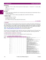
Table 2–3: L30 ORDER CODES (HORIZONTAL UNITS)
L30
-
*
**
- *
*
* - F
**
- H
**
- L
**
- N
**
- S
**
- U
**
- W/X
**
Full Size Horizontal Mount
BASE UNIT
L30
|
|
|
|
|
|
|
|
|
|
|
|
Base Unit
Содержание L30
Страница 10: ...x L30 Line Current Differential System GE Multilin TABLE OF CONTENTS ...
Страница 30: ...1 20 L30 Line Current Differential System GE Multilin 1 5 USING THE RELAY 1 GETTING STARTED 1 ...
Страница 58: ...2 28 L30 Line Current Differential System GE Multilin 2 4 SPECIFICATIONS 2 PRODUCT DESCRIPTION 2 ...
Страница 126: ...4 30 L30 Line Current Differential System GE Multilin 4 3 FACEPLATE INTERFACE 4 HUMAN INTERFACES 4 ...
Страница 370: ...5 244 L30 Line Current Differential System GE Multilin 5 10 TESTING 5 SETTINGS 5 ...
Страница 396: ...6 26 L30 Line Current Differential System GE Multilin 6 5 PRODUCT INFORMATION 6 ACTUAL VALUES 6 ...
Страница 450: ...10 10 L30 Line Current Differential System GE Multilin 10 4 INSTANTANEOUS ELEMENTS 10 APPLICATION OF SETTINGS 10 ...
Страница 464: ...A 10 L30 Line Current Differential System GE Multilin A 1 PARAMETER LISTS APPENDIX A A ...
Страница 600: ...C 30 L30 Line Current Differential System GE Multilin C 7 LOGICAL NODES APPENDIX C C ...
Страница 610: ...D 10 L30 Line Current Differential System GE Multilin D 1 IEC 60870 5 104 APPENDIX D D ...
Страница 622: ...E 12 L30 Line Current Differential System GE Multilin E 2 DNP POINT LISTS APPENDIX E E ...
Страница 634: ...F 12 L30 Line Current Differential System GE Multilin F 3 WARRANTY APPENDIX F F ...
Страница 644: ...x L30 Line Current Differential System GE Multilin INDEX ...