


4-30
Group 12 Monitoring Parameters
Param.
#
Parameters
Setting Range
Default
Unit
Control Mode
Notes
V/F
SLV
PMSLV
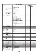
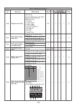
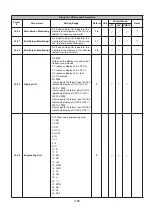
12-00
Display Screen (LED)
00000–88888
From the leftmost bit, sets the display
sequence when pressing the
MODE/PROG key.
0: no display
1: Output Current
2: Output Voltage
3: DC Bus Voltage
4: Heatsink Temperature*
5: PID Feedback
6: AI1 Value
7: AI2 Value
8: Counter Value
321
-
*1
*6
12-01
PID Feedback Display
Mode (LED)
0: Display the Feedback Value by
Integer (xxx)
0
-
*6
1: Display the Feedback Value by the
Value with One Decimal Place (xx.x)
2: Display the Feedback Value by the
Value with Two Decimal Places (x.xx)
12-02
PID Feedback Display
Unit Setting (LED)
0: xxxxx (no unit)
0
-
*6
1: xxxPb (pressure)
2: xxxFL (flow)
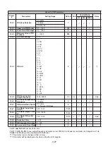
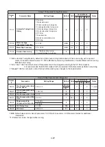
12-03
Line Speed Display
(LED)
0–60000
1500 /
1800
RPM
*1
*6
12-04
Modes of Line Speed
Display (LED)
0: Display AC Drive Output Frequency
0
-
*1
*6
1: Display Line Speed as integer
(xxxxx)
2: Display Line Speed with the First
Decimal Place (xxxx.x)
3: Display Line Speed with the Second
Decimal Place (xxx.xx)
4: Display Line Speed with the Third
Decimal Place (xx.xxx)
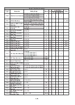
12-05
Status Display of Digital
Input & Output Terminal
(LED/LCD)
LCD display
LED Display
Correspondences to input and output
-
-
*9
0
0
0
0
0
0
0 0
N ot used
N ot used
Input T erm inal(S 6)
Input T erm inal(S 5)
Input T erm inal(S 4)
Input T erm inal(S 3)
Input T erm inal(S 2)
Input T erm inal(S 1)
0
:
O P E N
1
:
C LO S E
0
0
0
N ot used
O utput T erm inal(R 2)
O utput T erm inal(R 1)
0
O utput T erm inal(P LC )
S1 S2 S3 S4S5 S6S7 S8
R1
R2
PLC