


4-140
12-01
PID Feedback Display Mode (LED) Default: 0
Range
【
0
】
: Display the feedback value as integer (xxx)
【
1
】
: Display the feedback value with one decimal (xx.x)
【
2
】
: Display the feedback value with two decimals (x.xx)
12-02
PID Feedback Display Unit Setting (LED) Default: 0
Range
【
0
】
: xxxxx (no unit)
【
1
】
: xxxPb (pressure)
【
2
】
: xxxFL (flow)
12-03
Line Speed Display (LED) Default: 1500 / 1800
Range
【
0–60000
】
RPM
Set motor rated RPM for the AC Drive to display the actual motor speed based on the output frequency.
Motor synchronous speed = 120 x Rated frequency ÷ Number of poles.
12-04
Line Speed Display Mode (LED) Default: 0
Range
【
0
】
: Display AC Drive Output Frequency
【
1
】
: Line Speed Display at Integer. (xxxxx)
【
2
】
: Line Speed Display at One Decimal Place. (xxxx.x)
【
3
】
: Line Speed Display at Two Decimal Places. (xxx.xx)
【
4
】
: Line Speed Display at Three Decimal Places. (xx.xxx)
12-04≠0
, line speed is always displayed in run or stop mode. Set 12-03 to the maximum line speed that corresponds
to the maximum output frequency.
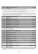
Example:
12-03 = 1800, the keypad display will show 900 when the output frequency is 30Hz on a 60Hz drive.
12-05
Status display of digital input terminal (LED/LCD) Default: –
Range
Read-only
Terminals S1-S6 are represented using two segments of each digit. Segment turns on when input is active. The
bottom segments of each of the first three digits are used to represent the digital outputs (R1, R2). Segments turn on
when output is active.
Example 1:
S1/S3/S5/S6 are ON, S2/S4 are OFF, 12-05 will turn on when RY1 without output. (LED)
S1 S2 S3 S4 S
RY1
RY2
PLC
Example 2:
S2/S3/S4 are ON, S1/S5/S6 are OFF, RY1/RY2 outputs are turned on.