


4-161
ASR Setting (SLV/PMSLV control mode)
In SLV mode the ASR gain is divided into a high-speed and low-speed section. The speed controller has a high-
speed gain (20-00 & 20-01) and a low-speed gain (20-02 & 20-03) that can be set independently.
a) The high/low switch frequency can be set with parameter 20-15 and 20-16. Similar to the ASR gain, the speed
estimator has a high-speed gain (20-09 & 20-10) and a low-speed gain (20-11 & 20-12).
b) The speed estimator has a low-pass filter to reduce speed feedback interference. Parameter 20-13 and 20-14 are
active at high speed as well as low speed. The switch between high-speed and low-speed is set by parameters
20-15 and 20-16.
c) 20-17 sets the low-speed compensation gain of the speed feedback.
d) 20-18 sets the high-speed compensation gain of the speed feedback.
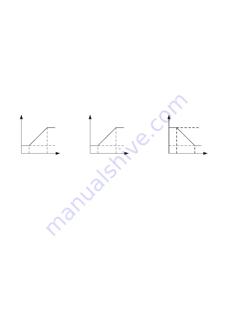
e) When the frequency reference rises above the value set in 20-16, the ASR gain used is set by parameters 20-00
and 20-01.
f) When the frequency reference falls below the value set in 20-15, the ASR gain used is set by parameters 20-02
and 20-03.
g) Gain time constant is adjusted linearly when the speed command falls within the range of 20-15 to 20-16, for a
smooth operation.
P,I
P,I
20-15
20-15
20-15
20-16
20-16
20-16
P = 20-00
I = 20-01
P = 20-00
I = 20-01
P = 20-02
I = 20-03
Frequency
Reference
20-13
20-14
Time
Constant
Frequency
Reference
Tuning the speed control gain
During ASR gain tuning, the multi-function analog output (AO1 terminal) can be used to monitor the output frequency
and motor speed (as shown in figure above).
SLV mode gain tuning (20-00 to 20-03, 20-09 to 20-18)
1) Tune the low-speed ASR P and I gain (20-02 & 20-03), make sure the reference frequency is set below the value
of parameter 20-15.
2) Tune the high-speed ASR PI gain 20-00 & 20-01, make sure the reference frequency is above the value set in
parameter 20-16 value.
3) Both low-speed ASR gain and the high-speed gain can be set to the same values and only require adjustment in
case of system instability.
4) Reduce the low-pass filter time constant 20-13 & 20-14 to decrease the bandwidth of the feedback system and re-
tune the ASR gain, if tuning the ASR P and I gain 20-00 to 20-03 does not improve the system response.
5) Tune low-speed low-pass filter time constant 20-14, make sure the reference frequency is below parameter 20-15
value.
6) Tune high-speed low-pass filter time constant 20-13 at frequency reference, make sure the reference frequency is
above parameter 20-16 value.
7) Increasing the low-pass filter time constant can limit the bandwidth of the speed feedback system and may reduce
the system response. Increasing the low-pass time reduces the speed feedback signal interference but may result
in sluggish system response when the load suddenly changes. Adjust the low-pass filter time if the load stays fairly
constant during normal operation. The low speed feedback bandwidth must be supported by the low ASR gain to
ensure the stable operation.
8) Decreasing the low-pass filter time constant may increase the bandwidth of the speed feedback and the system
response. Decreasing the low-pass time may increase the speed feedback interference resulting in system
instability when the load suddenly changes. Decreasing the low-pass filter time shortens system response time
and is required for rapidly changing loads. The high speed feedback bandwidth allows for a relatively high ASR
gain.