


4-14
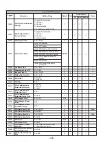
Group 03 External Digital Input and Output Parameters
Param.
#
Parameter Name
Setting Range
Default
Unit
Control mode
Notes
V/F
SLV
PM/SLV
03-08
S1
-
S6 scan time
1–200
1
-
03-09
S1– S4 switch type
select
xxx0b: S1 A Contact
xxx1b: S1 B Contact
xx0xb: S2 A Contact
xx1xb: S2 B Contact
x0xxb: S3 A Contact
x1xxb: S3 B Contact
0xxxb: S4 A Contact
1xxxb: S4 B Contact
0000b
-
03-10
S5– S6 switch type
select
xxx0b: S5A Contact
xxx1b: S5 B Contact
xx0xb: S6 A Contact
xx1xb: S6 B Contact
0000b
-
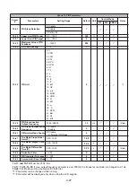
03-11
Relay (R1A-R1C) Output
0: During Running
1: Fault Contact Output
2: Frequency Agree
3: Setting Frequency Agree
(03-13±03-14)
4: Frequency Detection 1
(≥03-13+03-14)
5: Frequency Detection 2
(≤03-13+03-14)
6: Automatic Restart
7: Momentary AC Power Loss
8: Rapid Stop
9: Base Block
10: Motor Overload Protection (OL1)
11: Drive Overload Protection (OL2)
12: Over-torque Threshold Level (OL3)
13: Preset Output Current Reached
14: Brake Control
15: PID Feedback Signal Loss
16: Single pre-set count (3-22 & 3-23
)
17: Dual pre-set count (3-22 & 3-23)
18: PLC Status Indicator (00-02)
19: PLC control *
20: Zero Speed
30: Motor 2 Selection
54: Turn on short-circuit braking
55: Low Current Detection
59: Overheat Detection
1
-
See parameter
details
03-12
Relay (R2A-R2B) Output
0
-