


4-121
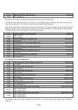
10 PID Parameters
10-00
PID target value source setting Default: 1
Range
【
0
】
: Keypad
【
1
】
: AI1 (Analog Input 1)
【
2
】
: AI2 (Analog Input 2)
【
3
】
: Communication
【
4
】
: Target Source set by 10-02
Parameter 10-00 sets the PID target selection. This is the value that the PID function will attempt to hold.
Note:
10-00 and 10-01 cannot be set to the same value or keypad will show an SE05 alarm.
10-01
PID feedback value source setting Default: 2
Range
【
0
】
: Keypad
【
1
】
: AI1 (Analog Input 1)
【
2
】
: AI2 (Analog Input 2)
【
3
】
: Communication
10-02
PID target value Default: 0
Range
【
0.00–100.00
】
%
For PID Setup, see the following essential
parameters:
10-00
: PID Target Value Source
10-01
: PID Feedback Value Source
10-02
: PID Target Value
10-03
: PID Control Mode
10-33
: Maximum Value of PID Feedback
10-34
: PID Feedback Value Scaling
PID Essentials
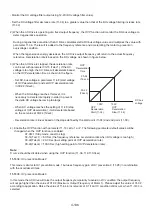
PID control is used to maintain a constant target variable such as pressure, flow, or temperature by regulating the
output frequency. A feedback device signal is used to compare the actual process variable to a specified target value.
The difference between the target value and the feedback signal is called the error signal.
For PID Tuning, see the following essential
parameters:
10-05
: Proportional Gain
10-06
: Integral Time
10-07
: Differential Time
00-14:
Acceleration Time
00-15
: Deceleration Time
Notes:
Changes to Group 09 require power cycling the AC drive to take effect.
Refer to Chapter 6 for additional communication details.
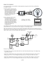
09-09
: AC Drive Transmission Wait Time (09-09).
This is the time between the controller message and the start of the AC Drive response message. Refer to Figure
below. Set the controller receive time-out to a greater value than the wait time parameter.
PLC Command
Information
Inverter response
information
Master
(PLC)
AC Drive
(TD400)
AC Drive
(TD400)
Master
(PLC)
3.5 Characters
09-09 set value