●
Install the covers and guards provided for this purpose before switching
on.
●
Never touch any electrical connection points of the components while
power is turned on.
●
Do not remove or plug in connectors when the component has been
powered.
●
Under specific conditions, electric drive systems can be operated at
mains protected by residual-current-operated circuit-breakers sensitive
to universal current (RCDs/RCMs).
●
Secure built-in devices from penetrating foreign objects and water, as
well as from direct contact, by providing an external housing, for
example a control cabinet.
High housing voltage and high leakage current! Danger to life, risk of injury
by electric shock!
●
Before switching on and before commissioning, ground or connect the
components of the electric drive and control system to the equipment
grounding conductor at the grounding points.
●
Connect the equipment grounding conductor of the components of the
electric drive and control system permanently to the main power supply
at all times. The leakage current is greater than 3.5 mA.
●
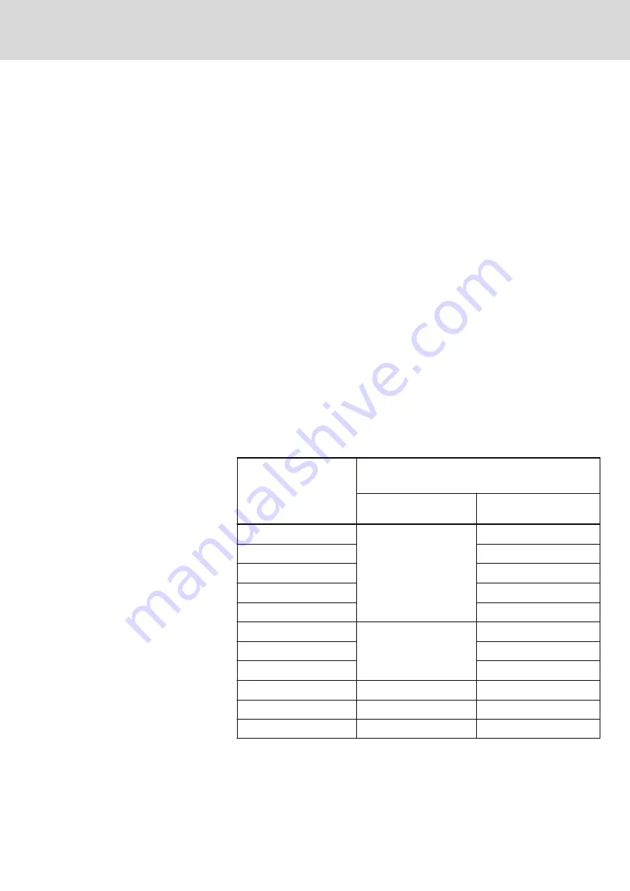
Establish an equipment grounding connection with a minimum cross
section according to the table below. With an outer conductor cross
section smaller than 10 mm
2
(8 AWG), the alternative connection of two
equipment grounding conductors is allowed, each having the same
cross section as the outer conductors.
Cross section outer
conductor
Minimum cross section equipment grounding conductor
Leakage current ≥ 3.5 mA
1 equipment grounding
conductor
2 equipment grounding
conductors
1.5 mm
2
(16 AWG)
10 mm
2
(8 AWG)
2 × 1.5 mm
2
(16 AWG)
2.5 mm
2
(14 AWG)
2 × 2.5 mm
2
(14 AWG)
4 mm
2
(12 AWG)
2 × 4 mm
2
(12 AWG)
6 mm
2
(10 AWG)
2 × 6 mm
2
(10 AWG)
10 mm
2
(8 AWG)
-
16 mm
2
(6 AWG)
16 mm
2
(6 AWG)
-
25 mm
2
(4 AWG)
-
35 mm
2
(2 AWG)
-
50 mm
2
(1/0 AWG)
25 mm
2
(4 AWG)
-
70 mm
2
(2/0 AWG)
35 mm
2
(2 AWG)
-
...
...
...
Tab. 3-1:
Minimum cross section of the equipment grounding connection
IndraDrive Mi Drive Systems with KCU02, KSM02,
KMS02/03, KMV03, KNK03, KLC03
39/407
Safety instructions for electric drives and controls
R911335703_Edition 04 Bosch Rexroth AG
Содержание Rexroth IndraDrive Mi KCU02
Страница 272: ...258 407 IndraDrive Mi Drive Systems with KCU02 KSM02 KMS02 03 KMV03 KNK03 KLC03 Bosch Rexroth AG R911335703_Edition 04 ...
Страница 290: ...276 407 IndraDrive Mi Drive Systems with KCU02 KSM02 KMS02 03 KMV03 KNK03 KLC03 Bosch Rexroth AG R911335703_Edition 04 ...
Страница 312: ...298 407 IndraDrive Mi Drive Systems with KCU02 KSM02 KMS02 03 KMV03 KNK03 KLC03 Bosch Rexroth AG R911335703_Edition 04 ...
Страница 378: ...364 407 IndraDrive Mi Drive Systems with KCU02 KSM02 KMS02 03 KMV03 KNK03 KLC03 Bosch Rexroth AG R911335703_Edition 04 ...
Страница 382: ...368 407 IndraDrive Mi Drive Systems with KCU02 KSM02 KMS02 03 KMV03 KNK03 KLC03 Bosch Rexroth AG R911335703_Edition 04 ...
Страница 408: ...394 407 IndraDrive Mi Drive Systems with KCU02 KSM02 KMS02 03 KMV03 KNK03 KLC03 Bosch Rexroth AG R911335703_Edition 04 ...
Страница 420: ...Notes 406 407 IndraDrive Mi Drive Systems with KCU02 KSM02 KMS02 03 KMV03 KNK03 KLC03 ...
Страница 421: ...Notes IndraDrive Mi Drive Systems with KCU02 KSM02 KMS02 03 KMV03 KNK03 KLC03 407 407 ...


