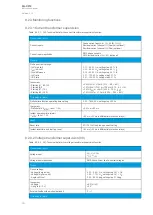
9.2.3 Monitoring functions
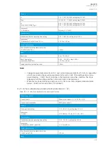
9.2.3.1 Current transformer supervision
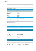
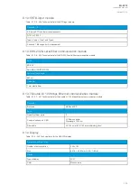
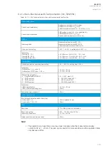
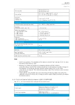
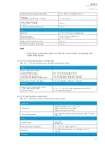
Table. 9.2.3.1 - 260. Technical data for the current transformer supervision function.
Measurement inputs
Current inputs
Phase current inputs: I
L1
(A), I
L2
(B), I
L3
(C)
Residual current channel I
01
(Coarse) (optional)
Residual current channel I
02
(Fine) (optional)
Current input magnitudes
RMS phase currents
RMS residual current (I
01
, I
02
) (optional)
Pick-up
Pick-up current settings:
- I
SET
high limit
- I
SET
low limit
- I
SUM
difference
- I
SET
ratio
- I2/I1 ratio
0.10…40.00 × I
N
, setting step 0.01 × I
N
0.10…40.00 × I
N
, setting step 0.01 × I
N
0.10…40.00 × I
N
, setting step 0.01 × I
N
0.01…100.00 %, setting step 0.01 %
0.01…100.00 %, setting step 0.01 %
Inaccuracy:
- Starting IL1, IL2, IL3
- Starting I2/I1
- Starting I01 (1 A)
- Starting I02 (0.2 A)
±0.5 %I
SET
or ±15 mA (0.10…4.0 × I
SET
)
±1.0 %I2
SET
/ I1
SET
or ±100 mA (0.10…4.0 × I
N
)
±0.5 %I0
SET
or ±3 mA (0.005…10.0 × I
SET
)
±1.5 %I0
SET
or ±1.0 mA (0.005…25.0 × I
SET
)
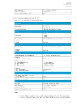
Time delay for alarm
Definite time function operating time setting
0.00…1800.00 s, setting step 0.005 s
Inaccuracy_
- Definite time (I
M
/I
SET
ratio > 1.05)
±2.0 % or ±80 ms
Instant operation time (alarm):
- I
M
/I
SET
ratio > 1.05
<80 ms (<50 ms in differential protection relays)
Reset
Reset ratio
97/103 % of the pick-up current setting
Instant reset time and start-up reset
<80 ms (<50 ms in differential protection relays)
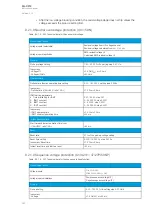
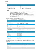
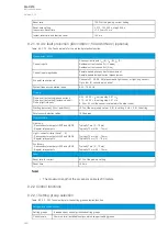
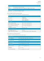
9.2.3.2 Voltage transformer supervision (60)
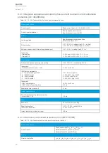
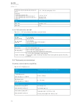
Table. 9.2.3.2 - 261. Technical data for the voltage transformer supervision function.
Measurement inputs
Voltage input
U
L1
, U
L2
, U
L3
U
L12
, U
L23
Voltage input magnitudes
RMS line-to-line or line-to-neutral voltages
Pickup
Pickup settings:
- Voltage (low pick-up)
- Voltage (high pick-up)
- Angle shift limit
0.05…0.50 × U
N
, setting step 0.01 × U
N
0.50…1.10 × U
N
, setting step 0.01 × U
N
2.00…90.00 deg, setting step 0.10 deg
Inaccuracy:
- Voltage
- U angle (U> 1 V)
±4.0 %U
SET
±3.0°
External line/bus side pickup (optional)
0
→
1
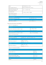
Time delay for alarm
A
AQ
Q-C213
-C213
Instruction manual
Version: 2.04
351
Содержание AQ-C213
Страница 1: ...AQ C213 Capacitor bank protection IED Instruction manual ...
Страница 308: ...Figure 7 4 184 Example block scheme A AQ Q C213 C213 Instruction manual Version 2 04 307 ...
Страница 330: ...Figure 8 14 207 Panel cutout dimensions and device spacing A AQ Q C213 C213 Instruction manual Version 2 04 329 ...

