


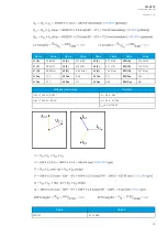

Figure. 5.2.2 - 67. Selecting the measured magnitude.
Voltage protection itself is based on the nominal voltage. A 20 000 V nominal voltage equals a 100 %
setting in voltage-based protection functions. A 120 % trip setting in the overvoltage stage equals to
24 000 V on the primary level (in this case a 20 % increase equals 4000 V).
Once the setting have been sent to the device, relay calculates the scaling factors and displays them
for the user. The "VT scaling factor P/S" describes the ratio between the primary voltage and the
secondary voltage. The per-unit scaling factors ("VT scaling factor p.u.") for both primary and
secondary values are also displayed.
The triggering of a voltage protection stage can be based on one, two, or three voltages (the "Pick-up
terms" setting at
Protection
→
Voltage
→
[protection stage menu]
→
Settings). Fault loops are either
line-to-line or line-to-neutral according to the "Measured magnitude" setting. As a default, the activation
of any one voltage trips the voltage protection stage.
Figure. 5.2.2 - 68. Selecting the operating mode.
There are several different ways to use all three voltage channels. The voltage measurement modes
are the following:
• 3LN
• 2LL+U0 (3LN)
A
AQ
Q-C213
-C213
Instruction manual
Version: 2.04
68
Содержание AQ-C213
Страница 1: ...AQ C213 Capacitor bank protection IED Instruction manual ...
Страница 308: ...Figure 7 4 184 Example block scheme A AQ Q C213 C213 Instruction manual Version 2 04 307 ...
Страница 330: ...Figure 8 14 207 Panel cutout dimensions and device spacing A AQ Q C213 C213 Instruction manual Version 2 04 329 ...


