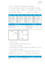
Name
Values
3PH (P)
17.32 MW
3PH (Q)
0.00 Mvar
3PH Tan
0.00
3PH Cos
0.87
5.2.4 Frequency tracking and scaling
Measurement sampling can be set to the frequency tracking mode or to the fixed user-
defined frequency sampling mode. The benefit of frequency tracking is that the measurements are
within a pre-defined accuracy range even when the fundamental frequency of the power system
changes.
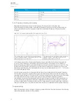
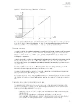
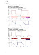
Table. 5.2.4 - 43. Frequency tracking effect (FF changes from 6 Hz to 75 Hz).
The measurement error with a fixed 50 Hz sampling frequency
when the frequency changes. The constant current is 5 A, the
frequency sweep is from 6 Hz to 75 Hz.
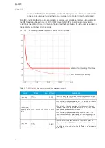
The measurement error with frequency tracking when the
frequency changes. The constant current is 5 A, the
frequency sweep is from 6 Hz to 75 Hz.
As the figures above show, the sampling frequency has a major effect on the relay's measurement
accuracy. If the sampling is not tracked to the system frequency, for example a 10 Hz difference
between the measured and the set system frequency can give a measurement error of over 5 %. The
figures also show that when the frequency is tracked and the sampling is adjusted according to the
detected system frequency, the measurement accuracy has an approximate error of 0.1...- 0.2 % error
in the whole frequency range.
AQ -200 series devices have a measurement accuracy that is independent of the system frequency.
This has been achieved by adjusting the sample rate of the measurement channels according to the
measured system frequency; this way the FFT calculation always has a whole power cycle in the buffer.
The measurement accuracy is further improved by Arcteq's patented calibration algorithms
that calibrate the analog channels against eight (8) system frequency points for both magnitude and
angle. This frequency-dependent correction compensates the frequency dependencies in the used,
non-linear measurement hardware and improves the measurement accuracy significantly. Combined,
these two methods give an accurate measurement result that is independent of the system frequency.
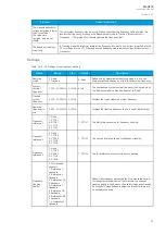
Troubleshooting
When the measured current, voltage or frequency values differ from the expected values, the following
table offers possible solutions for the problems.
A
AQ
Q-C213
-C213
Instruction manual
Version: 2.04
83
Содержание AQ-C213
Страница 1: ...AQ C213 Capacitor bank protection IED Instruction manual ...
Страница 308: ...Figure 7 4 184 Example block scheme A AQ Q C213 C213 Instruction manual Version 2 04 307 ...
Страница 330: ...Figure 8 14 207 Panel cutout dimensions and device spacing A AQ Q C213 C213 Instruction manual Version 2 04 329 ...


