Name
Range
Step Default
Description
U3 VT scaling
factor P/S U0/
SS
-
-
-
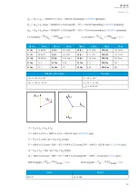
A relay feedback value; the calculated scaling factor that is the ratio
between the U3 channel's primary and secondary voltages. This setting is
only valid if the "2LL+U3" or the "2LN+U3" mode is selected.
U3 scaling
factor p.u. Pri
-
-
-
IED voltage channel U3 feedback value, scaling factor from p.u. value to
primary voltage. (Valid only in 2LL+U3 and 2LN+U3 mode)
U3 scaling
factor p.u. Sec -
-
-
IED voltage channel U3 feedback value, scaling factor from p.u. value to
secondary voltage. (Valid only in 2LL+U3 and 2LN+U3 mode)
Measurements
The following measurements are available in the measured voltage channels.
Table. 5.2.2 - 26. Per-unit voltage measurements.
Name
Unit
Range
Step
Description
Voltage Ux
("Ux Volt
p.u.")
×
U
N
0.00…500.0 0.01
The RMS voltage measurement (in p.u.) from each of the phase current
channels.
Voltage Ux
TRMS
("UxVolt
TRMS p.u.")
×
U
N
0.00…500.0 0.01
The TRMS current (inc. harmonics up to 31
st
) measurement (in p.u.) from each
of the phase current channels.
Table. 5.2.2 - 27. Secondary voltage measurements.
Name
Unit
Range
Step
Description
Secondary voltage
Ux
("Ux Volt sec")
V
0.00…500.0 0.01
The secondary RMS voltage measurement from each of the phase
current channels.
Secondary voltage
Ux TRMS
("UxVolt TRMS
sec")
V
0.00…500.0 0.01
The secondary TRMS current (inc. harmonics up to 31
st
) measurement
from each of the voltage channels.
Table. 5.2.2 - 28. Voltage phase angle measurements.
Name
Unit
Range
Step
Description
Ux Angle
deg
0.00…360.00
0.01
The phase angle measurement from each of the four voltage inputs.
Table. 5.2.2 - 29. Per-unit sequence voltage measurements.
Name
Unit
Range
Step
Description
Positive sequence
voltage
("Pos.seq.Volt.p.u.")
×
U
N
0.00…500.0 0.01
The measurement (in p.u.) from the calculated positive sequence
voltage.
Negative sequence
voltage
("Neg.seq.Volt.p.u.")
×
U
N
0.00…500.0 0.01
The measurement (in p.u.) from the calculated negative sequence
voltage.
Zero sequence voltage
("Zero.seq.Volt.p.u.")
×
U
N
0.00…500.0 0.01
The measurement (in p.u.) from the calculated zero sequence
voltage.
A
AQ
Q-C213
-C213
Instruction manual
Version: 2.04
73
Содержание AQ-C213
Страница 1: ...AQ C213 Capacitor bank protection IED Instruction manual ...
Страница 308: ...Figure 7 4 184 Example block scheme A AQ Q C213 C213 Instruction manual Version 2 04 307 ...
Страница 330: ...Figure 8 14 207 Panel cutout dimensions and device spacing A AQ Q C213 C213 Instruction manual Version 2 04 329 ...


