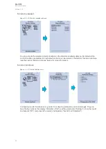
The "Digital outputs settings" subsection lets you select the polarity for each output; they can be either
Normal Open (NO) or Normal Closed (NC). The default polarity is Normal Open. The operational delay
of an output contact is approximately 5 ms. You can view the digital output statuses in the
corresponding subsection ("Digital output status"). The "Digital output descriptions" subsection allows
you to configure the description text for each output. All name changes affect the matrices as well as
input–output selection lists.
NO
NOTE!
TE!
An NC signal goes to the default position (NO) if the relay loses the auxiliary voltage or if the
system is fully reset. However, an NC signal does not open during voltage or during System
full reset. An NC output signal does not open during a Communication or Protection reset.
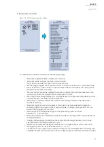
Figure. 4.5 - 33. LED settings section.
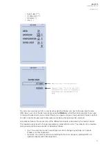
The "LED settings" section allows you to modify the individual label text attached to an LED ("LED
description settings"); that label is visible in the LED quick displays and the matrices. You can also
modify the color of the LED ("LED color settings") between green and yellow; by default all LEDs are
green.
A
AQ
Q-C213
-C213
Instruction manual
Version: 2.04
35
Содержание AQ-C213
Страница 1: ...AQ C213 Capacitor bank protection IED Instruction manual ...
Страница 308: ...Figure 7 4 184 Example block scheme A AQ Q C213 C213 Instruction manual Version 2 04 307 ...
Страница 330: ...Figure 8 14 207 Panel cutout dimensions and device spacing A AQ Q C213 C213 Instruction manual Version 2 04 329 ...


