


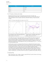
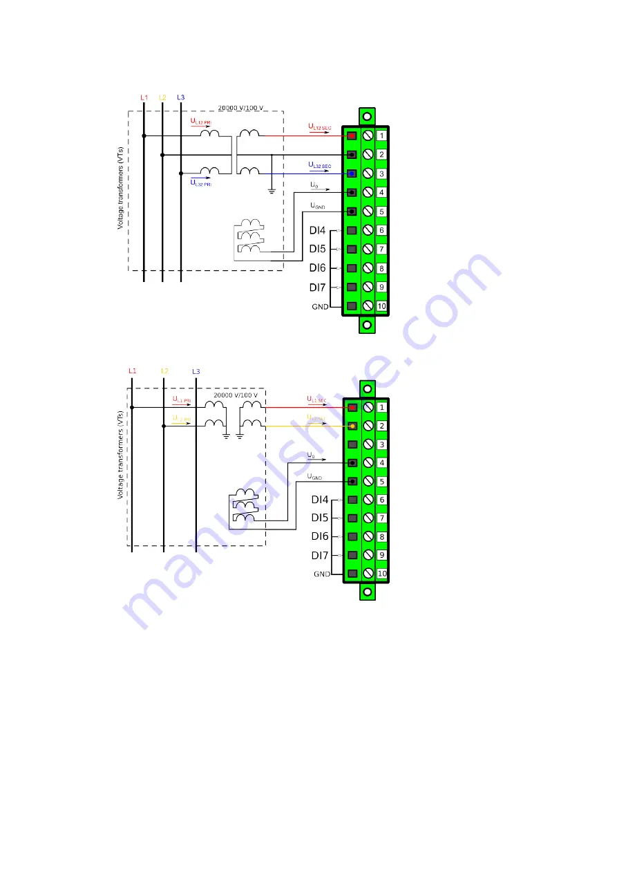
Figure. 5.2.2 - 71. Example connections for 2LL+U0 (open delta 2LL) voltage measurement.
Figure. 5.2.2 - 72. Example connections for 1LL+U0 voltage measurement.
If only two line-to-line voltages are measured, the third one is calculated based on the U12 and U23
vectors. When measuring line-to-line voltages, the line-to-neutral voltages can also be calculated as
long as the value of U0 is measured and known.
The voltage measurement channel U3 can also be used to measure the zero sequence voltage (U0)
when the "2LL+U0" or "1LL+U0" mode is selected.
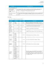
The image collection below presents the relay's behavior when nominal voltage is injected into the relay
via secondary test equipment while the relay is measuring line-to-neutral voltages (the mode is 3LN).
The VT scaling has been set to 20 000 : 100 V. The images also present a fraction of the available
information from the relay.
A
AQ
Q-C213
-C213
Instruction manual
Version: 2.04
70
Содержание AQ-C213
Страница 1: ...AQ C213 Capacitor bank protection IED Instruction manual ...
Страница 308: ...Figure 7 4 184 Example block scheme A AQ Q C213 C213 Instruction manual Version 2 04 307 ...
Страница 330: ...Figure 8 14 207 Panel cutout dimensions and device spacing A AQ Q C213 C213 Instruction manual Version 2 04 329 ...