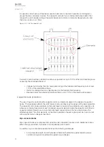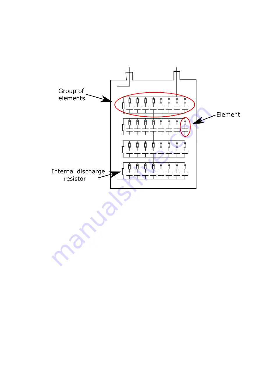
A capacitor unit is built up of individual capacitor elements connected in parallel, and arranged in
groups that are connected in series. The capacitor unit also has an internal discharge resistor that
reduces the unit's residual voltage. Capacitor banks are common in medium-voltage networks and
their size can be up to 1 Mvar.
Figure. 5.3.2 - 86. The capacitor unit.
Capacitor units should be suitable for continuous operation at up to 135 % of the rated reactive power
caused by the combined effects of:
• Voltage that is higher than the name plate rating at the fundamental frequency, but not over
110 % of the rated RMS voltage.
• Harmonic voltages that are superimposed on the fundamental frequency.
• Reactive power manufacturing tolerance that is up to 115 % of the rated reactive power.
Capacitor bank protection
The use of fuses for protecting the capacitor unit is an important subject in the design of capacitor
banks. The fuse design affects the unit's failure mode and influences the design of the bank protection.
The capacitor unit can be externally or internally fused. An external fuse protects each capacitor unit,
whereas an internal fuse protects each individual capacitor element inside the capacitor unit. When a
capacitor element failure occurs in an internally fused capacitor bank, the fuse only removes the
affected element. The other elements, connected in parallel in the same group, remain in service but
with a slightly higher voltage across them.
W
Wyyee-connect
-connected banks
ed banks
Wye capacitor banks are composed of capacitor units connected in series and in parallel per phase.
When the wye is earthed, it provides a low-impedance path to earth.
An earthed, wye-connected capacitor bank has the following advantages:
• A low-impedance path to earth provides inherent self-protection against lightning surge
currents and give some protection against surge voltages.
A
AQ
Q-C213
-C213
Instruction manual
Version: 2.04
95
Содержание AQ-C213
Страница 1: ...AQ C213 Capacitor bank protection IED Instruction manual ...
Страница 308: ...Figure 7 4 184 Example block scheme A AQ Q C213 C213 Instruction manual Version 2 04 307 ...
Страница 330: ...Figure 8 14 207 Panel cutout dimensions and device spacing A AQ Q C213 C213 Instruction manual Version 2 04 329 ...


