


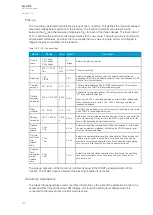
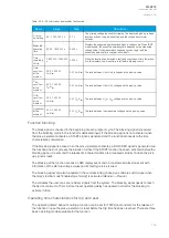

Table. 5.3.7 - 85. CBFP monitoring signal definitions.
Name
Description
Signal
in
monitor
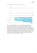
Defines which TRIP events of the used protection functions trigger the CBFP countdown. For the CBFP function to
monitor the signals selected here, the "Operation mode selection" parameter must be set to a mode that includes
signals (e.g. "Signals only", "Signals or DO", "Current and signals and DO").
Trip
monitor
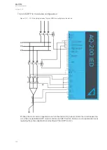
Defines which output relay of the used protection functions trigger the CBFP countdown. For the CBFP function to
monitor the output relays selected here, the "Operation mode selection" parameter must be set to a mode that
includes digital outputs (e.g. "DO only", "Current and DO", "Current or signals or DO").
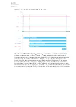
Pick-up
The setting parameters
I
set
and
I0
set
control the pick-up and the activation of the current-dependent
CBFP function. They define the minimum allowed measured current before action from the function.
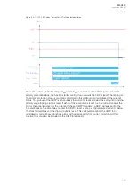
The function constantly calculates the ratio between the
I
set
or the
I0
set
and the measured magnitude
(
I
m
) for each of the three phases and the selected residual current input. The reset ratio of 97 % is built
into the function and is always relative to the
I
set
value. The setting value is common for all measured
phases. When the
I
m
exceeds the
I
set
value (in single, dual or all phases) it triggers the pick-up
operation of the function.
Table. 5.3.7 - 86. Operating mode and input signals selection.
Name
Range
Step Default
Description
I0Input
0: Not in use
1: I01
2: I02
3: I0Calc
-
0: Not
in use
Selects the residual current monitoring source, which can be either from the two
separate residual measurements (I01 and I02) or from the phase current's
calculated residual current.
Actmode
0: Current
only
1: DO only
2: Signals
only
3: Current
and DO
4: Current or
DO
5: Current
and signals
6: Current or
signals
7: Signals
and DO
8: Signals or
DO
9: Current or
DO or
signals
10: Current
and DO and
Signals
-
0:
Current
only
Selects the operating mode. The mode can be dependent on current
measurement, binary signal status, output relay status ("DO"), or a combination
of the three.
Table. 5.3.7 - 87. Pick-up settings.
Name
Range
Step
Default
Description
I
set
0.01…40.00×I
n
0.01×I
n
0.20×I
n
The pick-up threshold for the phase current measurement. This setting
limit defines the upper limit for the phase current pick-up element.
I0
set
0.005...40.000×I
n
0.001×I
n
1.200×I
n
The pick-up threshold for the residual current measurement. This setting
limit defines the upper limit for the phase current pick-up element.
A
AQ
Q-C213
-C213
Instruction manual
Version: 2.04
131
Содержание AQ-C213
Страница 1: ...AQ C213 Capacitor bank protection IED Instruction manual ...
Страница 308: ...Figure 7 4 184 Example block scheme A AQ Q C213 C213 Instruction manual Version 2 04 307 ...
Страница 330: ...Figure 8 14 207 Panel cutout dimensions and device spacing A AQ Q C213 C213 Instruction manual Version 2 04 329 ...


