5.3.9 Undervoltage protection (U<; 27)
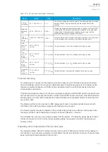
The undervoltage function is used for instant and time-delayed undervoltage protection. Each
device with a voltage protection module has four (4) available stages of the function (U>, U>>, U>>>,
U>>>>). The function constantly measures phase voltage magnitudes or line-to-line voltage
magnitudes. Undervoltage protection is based on line-to-line RMS voltage or to line-to-line RMS
voltage (as the user selects). If the protection is based on line-to-line voltage, undervoltage protection
is not affected by earth faults in isolated or compensated networks. Undervoltage protection has two
blocking stages: internal blocking (based on voltage measurement and low voltage), or external
blocking (e.g. during voltage transformer fuse failure). The blocking signal and the setting group
selection control the operating characteristics of the function during normal operation, i.e. the user or
user-defined logic can change function parameters while the function is running.
The outputs of the function are the START, TRIP and BLOCKED signals. The undervoltage function
uses a total of eight (8) separate setting groups which can be selected from one common source.
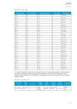
The function can operate on instant or time-delayed mode. In time-delayed mode the operation can be
selected between definite time (DT) mode and inverse definite minimum time (IDMT).
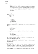
The operational logic consists of the following:
• input magnitude selection
• input magnitude processing
• threshold comparator
• two block signal check
• time delay characteristics
• output processing.
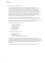
The inputs for the function are the following:
• operating mode selections
• setting parameters
• digital inputs and logic signals
• measured and pre-processed voltage magnitudes.
The function outputs the START, TRIP and BLOCKED signals which can be used for direct I/O
controlling and user logic programming. The function generates general time-stamped ON/OFF events
to the common event buffer from each of the three (3) output signals. In the instant operating mode the
function outputs START and TRIP events simultaneously with an equivalent time stamp. The time stamp
resolution is 1 ms. The function also a resettable cumulative counter for the START, TRIP and
BLOCKED events.
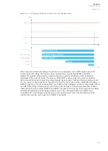
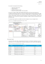
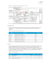
The following figure presents a simplified function block diagram of the undervoltage function.
A
AQ
Q-C213
-C213
Instruction manual
Version: 2.04
149
Содержание AQ-C213
Страница 1: ...AQ C213 Capacitor bank protection IED Instruction manual ...
Страница 308: ...Figure 7 4 184 Example block scheme A AQ Q C213 C213 Instruction manual Version 2 04 307 ...
Страница 330: ...Figure 8 14 207 Panel cutout dimensions and device spacing A AQ Q C213 C213 Instruction manual Version 2 04 329 ...


