5.3.2.1 Capacitor bank overload protection (Icol>; 49OL)
Capacitor bank overload protection is used for overload alarming and capacitor bank protection. The
main difference to the overcurrent protection function is the possibility to freely program the capacitor
overload curve to the function by giving the current or time points to the function or the IDMT formula
coefficients. The operating decisions are based on the phase current magnitude, which is constantly
measured by the function. The phase current magnitudes available are equal to the RMS values, to
TRMS values (including harmonics up to 32
nd
), or to peak-to-peak values. The blocking signal and the
setting group selection control the operating characteristics of the function during normal operation,
i.e. the user or user-defined logic can change the function parameters while the function is running.
The outputs of the function are the START, TRIP and BLOCKED signals. The capacitor bank overload
function uses a total of eight (8) separate setting groups which can be selected from one common
source.
The function can operate on instant or time-delayed mode. In time-delayed mode the operation can be
selected between definite time (DT) mode and inverse definite minimum time (IDMT) mode. The IDMT
operation supports both IEC and ANSI standard time delays as well as custom parameters. The
function includes CT saturation checking which allows the function to start and operate accurately
during CT saturation.
The operational logic consists of the following:
• input magnitude selection
• input magnitude processing
• saturation check
• threshold comparator
• block signal check
• time delay characteristics
• output processing.
The basic design of the protection function is the three-pole operation.
The inputs for the function are the following:
• operating mode selections
• setting parameters
• digital inputs and logic signals
• measured and pre-processed current magnitudes.
The function outputs the START, TRIP and BLOCKED signals which can be used for direct I/O
controlling and user logic programming. The function generates general time-stamped ON/OFF events
to the common event buffer from each of the three (3) output signals. In the instant operating mode the
function outputs START and TRIP events simultaneously with an equivalent time stamp. The time stamp
resolution is 1 ms. The function also provides a resettable cumulative counter for the START, TRIP and
BLOCKED events.
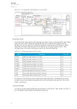
The following figure presents a simplified function block diagram of the capacitor bank overload
function.
A
AQ
Q-C213
-C213
Instruction manual
Version: 2.04
98
Содержание AQ-C213
Страница 1: ...AQ C213 Capacitor bank protection IED Instruction manual ...
Страница 308: ...Figure 7 4 184 Example block scheme A AQ Q C213 C213 Instruction manual Version 2 04 307 ...
Страница 330: ...Figure 8 14 207 Panel cutout dimensions and device spacing A AQ Q C213 C213 Instruction manual Version 2 04 329 ...

