


Event Number
Event channel
Event block name
Event Code
Description
2245
35
CUB4
5
Block OFF
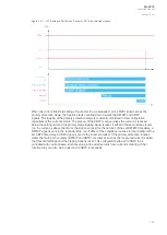
The function registers its operation into the last twelve (12) time-stamped registers. The register of the
function records the ON event process data for START, TRIP or BLOCKED. The table below
presents the structure of the function's register content.
Table. 5.3.5 - 77. Register content.
Date and
time
Event
code
Fault
type
Trigger
current
Fault
current
Pre-fault
current
Fault
currents
Trip time
remaining
Used SG
dd.mm.yyyy
hh:mm:ss.mss
2048-2245
Descr.
Unbalance
Start
average
current
Trip
-20ms
averages
Start
-200ms
averages
I1, I2, IZ
mag. and
ang.
0
ms...1800s
Setting
group 1...8
active
5.3.6 Harmonic overcurrent protection (Ih>; 50H/51H/68H)
The harmonic overcurrent function is used for non-directional instant and time-delayed overcurrent
detection and clearing. The number of stages in the function depends on the relay model. The function
constantly measures the selected harmonic component of the selected measurement channels, the
value being either absolute value or relative to the RMS value. The blocking signal and the setting
group selection control the operating characteristics of the function during normal operation, i.e. the
user or user-defined logic can change function parameters while the function is running.
The outputs of the function are the START, TRIP and BLOCKED signals. The non-directional
harmonic overcurrent function uses a total of eight (8) separate setting groups which can be selected
from one common source.
The function can operate on instant or time-delayed mode. Either START or TRIP signal can be used
when the instant mode is selected to block other protection stages. In time-delayed mode the
operation can be selected between definite time (DT) mode and inverse definite minimum time (IDMT)
mode. The START signal can be used to block other stages; if the situation lasts longer, the TRIP signal
can be used on other actions as time-delayed.The IDMT operation supports both IEC and ANSI
standard time delays as well as custom parameters.
The operational logic consists of the following:
• input magnitude selection
• input magnitude processing
• saturation check
• threshold comparator
• block signal check
• time delay characteristics
• output processing.
The basic design of the protection function is the three-pole operation.
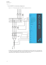
The inputs of the function are the following:
• operating mode selections
• setting parameters
• digital inputs and logic signals
• measured and pre-processed current magnitudes.
A
AQ
Q-C213
-C213
Instruction manual
Version: 2.04
122
Содержание AQ-C213
Страница 1: ...AQ C213 Capacitor bank protection IED Instruction manual ...
Страница 308: ...Figure 7 4 184 Example block scheme A AQ Q C213 C213 Instruction manual Version 2 04 307 ...
Страница 330: ...Figure 8 14 207 Panel cutout dimensions and device spacing A AQ Q C213 C213 Instruction manual Version 2 04 329 ...


