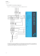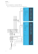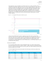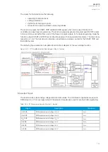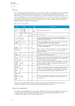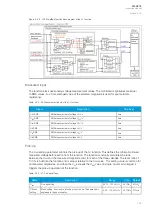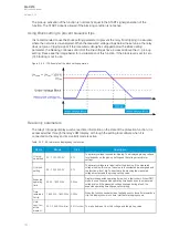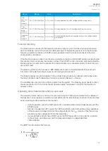
Trip and CBFP in the device configuration
Figure. 5.3.7 - 101. Wiring diagram when Trip and CBFP are configured to the device.
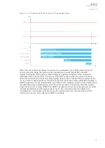
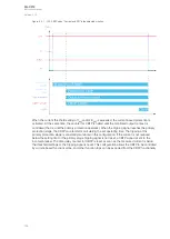
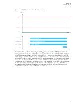
Probably the most common application is when the device's trip output controls the circuit breaker trip
coil, while one dedicated CBFP contact controls the CBFP function. Below are a few operational cases
regarding the various applications and settings of the CBFP function.
A
AQ
Q-C213
-C213
Instruction manual
Version: 2.04
137
Содержание AQ-C213
Страница 1: ...AQ C213 Capacitor bank protection IED Instruction manual ...
Страница 308: ...Figure 7 4 184 Example block scheme A AQ Q C213 C213 Instruction manual Version 2 04 307 ...
Страница 330: ...Figure 8 14 207 Panel cutout dimensions and device spacing A AQ Q C213 C213 Instruction manual Version 2 04 329 ...


