


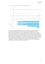


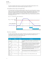


• Instant operation: gives the TRIP signal with no additional time delay simultaneously with the
START signal.
• Definite time operation (DT): gives the TRIP signal after a user-defined time delay regardless
of the measured voltage as long as the voltage is above the
U
set
value and thus the pick-up
element is active (independent time characteristics).
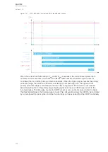
• Inverse definite minimum time (IDMT): gives the TRIP signal after a time which is in relation
to the set pick-up voltage
U
set
and the measured voltage
U
m
(dependent time
characteristics).
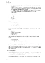
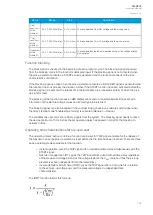
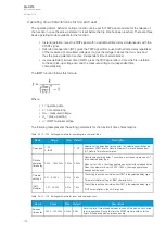
The IDMT function follows this formula:
Where:
•
t = operating time
•
k = time dial setting
•
U
m
= measured voltage
•
U
s
= pick-up setting
•
a = IDMT multiplier setting
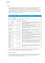
The following parameters are for setting the operating time characteristics (can be found in the Pick-up
settings):
• Delay type
• Definite operating time delay
• Time dial setting k
• IDMT multiplier
The following parameters are for resetting the time characteristics (can be found in the Pick-up
settings):
• Release time delay
• Delayed pick-up release
• Operating time calc reset after release time
• Continue time calculation during release time
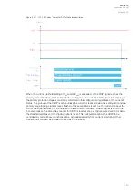
The user can reset characteristics through the application. The default setting is a 60 ms delay; the
time calculation is held during the release time.
In the release delay option the operating time counter calculates the operating time during the release.
When using this option the function does not trip if the input signal is not re-activated while the release
time count is on-going.
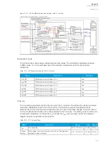
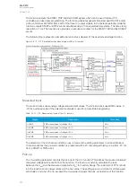
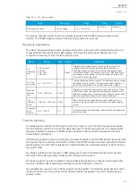
Events and registers
The overvoltage function (abbreviated "OV" in event block names) generates events and registers from
the status changes in START, TRIP, and BLOCKED. The user can select which event messages are
stored in the main event buffer: ON, OFF, or both. The function offers four (4) independent stages;
the events are segregated for each stage operation.
The events triggered by the function are recorded with a time stamp and with process data values.
A
AQ
Q-C213
-C213
Instruction manual
Version: 2.04
147
Содержание AQ-C213
Страница 1: ...AQ C213 Capacitor bank protection IED Instruction manual ...
Страница 308: ...Figure 7 4 184 Example block scheme A AQ Q C213 C213 Instruction manual Version 2 04 307 ...
Страница 330: ...Figure 8 14 207 Panel cutout dimensions and device spacing A AQ Q C213 C213 Instruction manual Version 2 04 329 ...


