A96G140/A96G148/A96A148 User’s manual
7. Interrupt controller
81
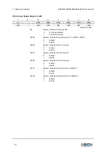
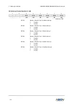
EIFLAG1 (External Interrupt Flag 1 Register): A6H
7
6
5
4
3
2
1
0
T0OVIFR
T0IFR
–
–
FLAG12
FLAG11
FLAG10
FLAG8
R/W
R/W
–
–
R/W
R/W
R/W
R/W
Initial value: 00H
T0OVIFR
When T0 overflow interrupt occurs, this bit becomes
‘1’. For clearing
bit, write
‘0’ to this bit or automatically clear by INT_ACK signal.
Writing
“1” has no effect.
0
T0 overflow Interrupt no generation
1
T0 overflow Interrupt generation
T0IFR
When T0 interrupt occurs, this bit becomes
‘1’. For clearing bit, write
‘0’ to this bit or automatically clear by INT_ACK signal. Writing “1” has
no effect.
0
T0 Interrupt no generation
1
T0 Interrupt generation
EIFLAG1[3:0]
When an External Interrupt (EINT8, EINT10-EINT12) is occurred, the
flag becomes
‘1’. The flag is cleared by writing ‘0’ to the bit or
automatically cleared by INT_ACK signal. Writing
“1” has no effect.
0
External Interrupt not occurred
1
External Interrupt occurred
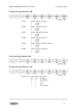
EIPOL1 (External Interrupt Polarity 1 Register): A7H
7
6
5
4
3
2
1
0
POL12
POL11
POL10
POL8
R/W
R/W
R/W
R/W
R/W
R/W
R/W
R/W
Initial value: 00H
EIPOL1[7:0]
External interrupt (EINT8,EINT10,EINT11,EINT12) polarity selection
POLn[1:0]
Description
0
0
No interrupt at any edge
0
1
Interrupt on rising edge
1
0
Interrupt on falling edge
1
1
Interrupt on both of rising and falling edge
Where n =8, 10, 11 and 12


